70 LED Matrix In A Jack-o-lantern

What takes eight hours to solder and uses more shrink tubing that you thought imaginable? An LED matrix installed in a real pumpkin. When I mentioned that we’d like the LED pumpkin in last Friday’s post scaled up to a full LED matrix I had no idea it would be me doing the work. But [Caleb] and I thought it might be just the thing to present for the hacker’s favorite holiday.

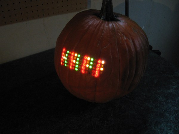
Installed in the autumn vegetable is a marquee made from a 5×14 matrix of light emitting diodes. I spaced them by printing out a grid on the computer, taping it to the pumpkin, and drilling 70 holes in the front of the thing. The real trouble came when inserting all of the LEDs from the inside; each of them has four wires soldered to it, creating a net of black wiring. Above you can see it turned out great. This is a shot of it scrolling the message HAPPY HALLOWEEN.

Join us after the break for video of this prop. But we’re not just sharing the finished product. I’ll take you through the build process. Along the way you’ll learn the design considerations that go into an LED matrix and how you can use these techniques to build your own in any size and configuration you desire.

Continue reading “70 LED Matrix In A Jack-o-lantern”

RGB LED Headband

Hard to imagine this going on business trips to Shangai

[Johncon] wrote this fantastic instructible showing us how to make an RGB LED headband. This should come in really handy the next time we find ourselves needing one… it happens. He picked up this little RGB LED strip while on a business trip to Shanghai. He had to reverse engineer the chip that controls each pair, but once that was done there wasn’t much left to do. He’s using a picaxe microcontroller since he had some lying around and, as he points out, they require very little external hardware.

He says he’s going to be ordering more of this LED strip soon and is willing to make a group buy if anyone is interested.

[via MakeZine]

Halloween Props: Pumpkin In Standby-mode

Evil Mad Scientist Laboratories is preparing for Halloween with this standby-mode pumpkin. Inside there’s an LED plugging a hole that is drilled just to the skin of the gourd-like vegetable. It fades in and out similar to a sleeping Mac, using what we think is a vastly over-powered circuit based on an ATtiny2313 (1k  of programming space for this?). But we still like the idea and we’d enjoy seeing it scaled up to a full LED matrix.

We’ve come to expect pumpkin hacks from EMSL and they don’t disappoint. Last year was a mechanized version, and the year before an LED schematic symbol. So what about your creation? With about one week left, take a look around and see if you can’t create something as wonderful as the Pie of Sauron.

Multiple Core Propeller Speeds Up Display Addressing

Th

If you ever wondered what an eight-core Propeller processor can do for you, [Tom] found one answer. He’s using the multiple cores to individually address serial displays. He has six display modules, and each of them incorporate six 8×8 LED modules. This makes for a total of 2304 LEDs, and since they’re addressed by cascading serial data, that means 2304 bytes pushed to the display. You’re going to suffer from quite a bit of slow-down if you choose that communication method.

This is where multiple-cores come in handy. Instead of cascading data between the six modules, he assigned a different core to each. Now he can concurrently address the six displays, reducing his serial data from 2304 bits per frame down to 384 bits per frame. As you can see in the video after the break, updating the display six times as fast as before yields fantastic results.

Now what if you’re using a processor that has forty of these multi-core Propeller chips?

This does make us wonder, can’t the same thing be done on a single-core processor? An eight-bit device takes one cycle to set all eight bits on a single port. So why not just connect the six serial connections on six bits of the same port? Weigh in with your thoughts in the comments.

Continue reading “Multiple Core Propeller Speeds Up Display Addressing”

Syyn Labs’ Glowing DNA

This beautiful music syncronized double helix was made by Syyn labs. Last time we saw them, they had created that amazing rube goldberg style music video for OK Go. This 100 foot long LED DNA strand took over 1000 combined man hours to build. It took 512 LEDs, 32 LED controllers, 4 Arduinos, 4 computers, over a mile of wire and a very dedicated team, which included [Eliot Phillips]. It takes input from beatmatching/VU software as well as a 32 button console or an iPad. You can catch a video of it in action after the break, and they plan on releasing a timelapse of the build in the near future.

Continue reading “Syyn Labs’ Glowing DNA”

Spinning POV Clock Done Oh-so-right

[Kizo] built an extraordinary persistence of vision clock. The design uses a PC cooling fan to spin the propeller-like PCB. As it goes around, a hall effect sensor synchronizes the illumination of the LEDs to draw the display. Power for the rotating electronics is transferred wirelessly via a transformer on the base and coil on the spinning board. The final version uses an ATmega324 microcontroller running at 20 MHz and has an IR receiver for changing the settings. The 3000 lines of code bring a lot of bells and whistles, including a menu system with a huge amount of settings from tweaking the clock display, to font selection for scrolling messages. Take a look at the demo after the break. The double-sided board looks like it’s pretty difficult to etch at home, but as you can see from the forum post (translated), [Kizo] did a great job on this build from start to finish. Continue reading “Spinning POV Clock Done Oh-so-right”

DIY Night Vision Monocle

This interesting mashup shows it’s easy to make your own night vision goggles. It makes use of just a few parts; the viewfinder from an old camcorder, a low-light security camera module, and a collection of infrared LEDs.

The low-light camera is capable of detecting infrared light, which is invisible to our eyes. If you shine the right IR LEDs on an object, they will cast enough light for the camera to clearly view the objects around you. The camcorder viewfinder is nothing more than a compact way to display what the camera sees. This would be easy to accomplish with a wearable display. It is also beneficial to have a large IR light source so you may consider modifying that giant LED flashlight you’ve been meaning to build so that it operates in the infrared wavelengths.

This project comes from the same source as the Laser Microphone we looked in on last month. Just like that one, there’s plenty of extra information about this build. There’s suggestions for choosing and focusing a light source. This includes using lasers as the source, and binoculars for long-range viewing.