Normally, when a project calls for addressable LEDs, we just throw a strip of WS2812s and an Arduino together, cobble together some code from the examples in the FastLED library, and call it a day. We don’t put much thought into what’s going on under the hood, unless and until we run into an LED project that’s a little more challenging.
Inventor [Leo Fernekes] found himself in such a situation recently, when he pitched in on an LED art installation. The project called for rings of LED bars around the trunks of trees on a private estate. The physical size of the project and the aesthetic requirements created significant challenges, though. One of these was finding a way to control the LED bars, each of which draws about 100 mA and needs to be very smoothly dimmed. [Leo] looked at the WS2811 LED driver, but found that the low drive current and the 8-bit PWM output failed to tick either of those boxes.
[Leo] solved both problems by using two of the three PWM channels on the chip in concert — one to control the current and one to PWM the LED. The circuit he came up with is deceptively simple — just four transistors, a Schottky diode, and a bunch of passives. The other clever bit is the data interface between LED bars, which can be configured as either single-ended or differential. This allows the same interface to be used for the short distance between bars on a tree, and the longer runs between trees.
As usual, [Leo] does a great job of explaining his design and how it works, which we find very instructional. He did something similar when he managed to dim a non-dimmable LED fixture.
The remarkable thing about our universe is that it’s possible to explore at least some of its inner workings with very simple tools. Gravity is one example, to which [Galileo]’s inclined planes and balls bear witness. But that’s classical mechanics: surely the weirdness that is quantum mechanics requires far more sophisticated instrumentation to explore, right?
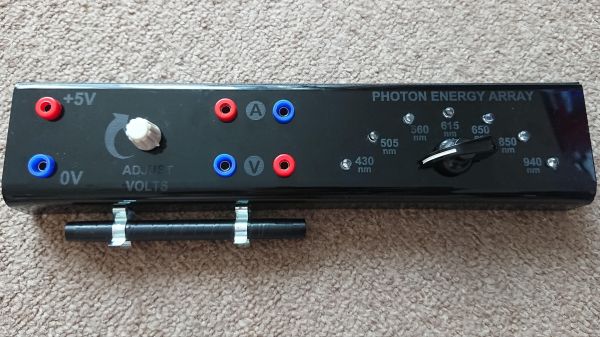
That’s true enough — if you consider a voltmeter and a Mark 1 eyeball to be sophisticated. That’s pretty much all you need for instruments to determine Planck’s constant to a decent degree of precision, the way that [poblocki1982]’s did. There’s a little more to it, of course; the method is based on measuring the voltage at which LEDs of various wavelengths start shining, so a simple circuit was built to select an LED from the somewhat grandly named “photon energy array” and provide a way to adjust and monitor the voltage and current.
By performing the experiment in a dark room with adapted eyes, or by using an opaque tube to block out stray light, it’s possible to slowly ramp the voltage up until the first glimmer of light is seen from each LED. Recording the voltage and the wavelength gives you the raw numbers to calculate the Planck constant h, as well as the Planck error Δh, with the help of a handy spreadsheet. [poblocki1982] managed to get within 11% of the published value — not too shabby at all.
It’s pretty amazing how quickly light-emitting diodes went from physics lab curiosity to a mainstream commodity product made in the millions, if not billions. Everything about LEDs has gotten better, smaller, and cheaper over the years, going from an “any color you want as long as it’s red” phase to all the colors of the rainbow and beyond in a relatively short time. LEDs have worked their way into applications that just didn’t seem likely not that long ago, like architectural lighting, automotive applications, and even immense displays covering billboards, buildings, and sporting venues with multicolor, high-resolution displays.
It’s that latter application that seems to have provided a boon to electronics hobbyists, in the form of cheap and plentiful LED matrix modules. These are easily sourced at the usual places, and with their tightly packed pinpoints that can show any color at any intensity, they have a ton of fun and useful applications for the hacker. But how exactly do you put them to use? Usually the electronics end is pretty straightforward, but some of the math involved in figuring out how to address all these LEDs can be a little mind-bending.
To help us sort all this out, Garrett Mace will drop by the Hack Chat. You’ve probably seen Garrett’s cool LED matrix shades, which have gone through a ton of revisions and are a much-copied fashion accessory among the cool hackers. They look simple, but there are tricks to making them work right, and Garrett will share his secrets. Come with your questions on putting LED matrix modules to work, especially those odd-size modules and strange arrangements that defy simple Cartesian coordinates.
Click that speech bubble to the right, and you’ll be taken directly to the Hack Chat group on Hackaday.io. You don’t have to wait until Wednesday; join whenever you want and you can see what the community is talking about.
We love to see LEDs combined in all shapes and sizes, so we were especially ticked when we caught a glimpse of [Debra Ansell]’s (also known as [GeekMomProjects]) interlocking triangular TriangleLightPanel system glowing on our screen. This unusually shaped array seemed to be self supporting and brightly glowing, so we had to know more.
The TriangleLightPanel is a single, triangular, light panel (refreshing when everything is in the name, isn’t it?). Each panel consists of a single white PCBA holding three side-firing SK6812 LEDs aimed inward, covered by transparent acrylic. When the LEDs are doing their thing, the three-position arrangement and reflective PCB surface does diffuses the light sufficiently to illuminate each pane — if not perfectly evenly — very effectively. Given the simple construction it’s difficult to imagine how they could be significantly improved.
The real trick is the mechanical arrangement. Instead of being connected with classic Dupont jumper wires and 0.1″ headers or some sort of edge connector, [Debra] used spring contacts. But if you’re confused by the lack of edge-plated fingers think again; the connectors are simple plated strips on the back. There is a second PCBA which effectively acts as wires and a surface to mount the spring contacts on, which is bolted onto the back of the connected leaves to bridge between each node. The tiles need to be mechanically connected in any case, so it’s a brilliantly simple way to integrate the electrical connection with the necessary mechanical one.
All the requisite source files are available on the project’s GitHub page and the original Tweets announcing the project are here for reference. We can’t wait to see what this would look like with another 30 or 40 nodes! Enterprising hackers are already building their own setup; see [arturo182]’s 24 tile array glowing after the break.
That collective “Phew!” you heard this week was probably everyone on the Mars Ingenuity helicopter team letting out a sigh of relief while watching telemetry from the sixth and somewhat shaky flight of the UAV above Jezero crater. With Ingenuity now in an “operations demonstration” phase, the sixth flight was to stretch the limits of what the craft can do and learn how it can be used to scout out potential sites to explore for its robot buddy on the surface, Perseverance.
While the aircraft was performing its 150 m move to the southwest, the stream from the downward-looking navigation camera dropped a single frame. By itself, that wouldn’t have been so bad, but the glitch caused subsequent frames to come in with the wrong timestamps. This apparently confused the hell out of the flight controller, which commanded some pretty dramatic moves in the roll and pitch axes — up to 20° off normal. Thankfully, the flight controller was designed to handle just such an anomaly, and the aircraft was able to land safely within five meters of its planned touchdown. As pilots say, any landing you can walk away from is a good landing, so we’ll chalk this one up as a win for the Ingenuity team, who we’re sure are busily writing code to prevent this from happening again.
If wobbling UAVs on another planet aren’t enough cringe for you, how about a blind mechanical demi-ostrich drunk-walking up and down a flight of stairs? The work comes from the Oregon State University and Agility Robotics, and the robot in question is called Cassie, an autonomous bipedal bot with a curious, bird-like gait. Without cameras or lidar for this test, the robot relied on proprioception, which detects the angle of joints and the feedback from motors when the robot touches a solid surface. And for ten tries up and down the stairs, Cassie did pretty well — she only failed twice, with only one counting as a face-plant, if indeed she had a face. We noticed that the robot often did that little move where you misjudge the step and land with the instep of your foot hanging over the tread; that one always has us grabbing for the handrail, but Cassie was able to power through it every time. The paper describing how Cassie was trained is pretty interesting — too bad ED-209’s designers couldn’t have read it.
So this is what it has come to: NVIDIA is now purposely crippling its flagship GPU cards to make them less attractive to cryptocurrency miners. The LHR, or “Lite Hash Rate” cards include new-manufactured GeForce RTX 3080, 3070, and 3060 Ti cards, which will now have reduced Ethereum hash rates baked into the chip from the factory. When we first heard about this a few months ago, we puzzled a bit — why would a GPU card manufacturer care how its cards are used, especially if they’re selling a ton of them. But it makes sense that NVIDIA would like to protect their brand with their core demographic — gamers — and having miners snarf up all the cards and leaving none for gamers is probably a bad practice. So while it makes sense, we’ll have to wait and see how the semi-lobotomized cards are received by the market, and how the changes impact other non-standard uses for them, like weather modeling and genetic analysis.
Speaking of crypto, we found it interesting that police in the UK accidentally found a Bitcoin mine this week while searching for an illegal cannabis growing operation. It turns out that something that uses a lot of electricity, gives off a lot of heat, and has people going in and out of a small storage unit at all hours of the day and night usually is a cannabis farm, but in this case it turned out to be about 100 Antminer S9s set up on janky looking shelves. The whole rig was confiscated and hauled away; while Bitcoin mining is not illegal in the UK, stealing the electricity to run the mine is, which the miners allegedly did.
And finally, we have no idea what useful purpose this information serves, but we do know that it’s vitally important to relate to our dear readers that yellow LEDs change color when immersed in liquid nitrogen. There’s obviously some deep principle of quantum mechanics at play here, and we’re sure someone will adequately explain it in the comments. But for now, it’s just a super interesting phenomenon that has us keen to buy some liquid nitrogen to try out. Or maybe dry ice — that’s a lot easier to source.
[Maarten Tromp]’s replacement of his motorcycle’s tail light with LED equivalents is a great example of something that every hacker learns sooner or later: interfacing to and working around existing parts can turn a trivial-seeming task into a much bigger job than expected. The more one has to work within the constraints of an existing system, the more opportunities there are for roadblocks and surprise issues to stall progress, and this project is a great example of that.
[Maarten]’s 1999 Honda ST1100 Pan European motorcycle had no aftermarket options for an LED rear light assembly, and he wasn’t too keen on just installing a generic module to replace the original. Instead, he resolved to purchase and disassemble a used factory assembly, and replace the incandescent lamps with some equivalent LEDs. Replacing bulbs with LEDs sounds easy, but doing the job right took [Maarten] almost two weeks in the end.
Problems started early with simple things like how to open up the light assembly itself. The unit isn’t user-serviceable and isn’t intended to be opened, and the parts are sealed shut with a waxy substance. Fortunately, heat does the trick. Another early hitch was the curved base of the light assembly, which made mounting flat perfboard or veroboard a challenge. In the end, [Maarten] settled on a triangular grid of high-brightness LEDs, driven with LM317 regulators configured as constant-current supplies, mounted on some protoboard cut to fit the unique curve of the assembly. The result accepts the wide voltage range of the motorcycle’s battery (from 10.5 V to 14.5 V) and can still function even if some individual LEDs stop working.
The project has one more example of how working around existing hardware can be a pain. [Maarten] had originally intended to swap out the turn signal lamps for LEDs as well, but there is a glitch. The motorcycle’s turn signal relay will do a fast blink pattern if burnt-out turn signal lamps are detected. Since LEDs consume considerably less current than the original bulbs, the relay will remain stuck in the fault condition. There are a few different ways around this, but it’s a problem for another day. For now, the tail light LED replacement is a success.
Working around existing hardware frequently brings unexpected challenges, but when safety systems (such as lights on a vehicle) are involved, it’s extra-important to make sure things are done right.
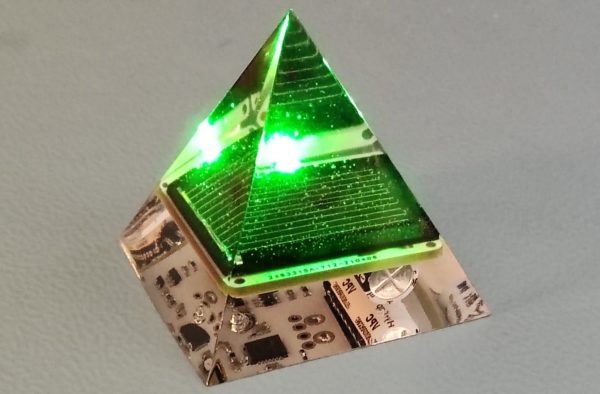
Without knowing it, we’ve spent years watching [Jasper Sikken] piece together an empire of energy harvesting equipment, and now he’s putting the pieces together into wonderful creations. His recently finished solar harvesting pyramids are mesmerizing objects of geometric perfection we’d love to see glinting in the sun.
These solar harvesting pyramids are well described by their name. Each one contains a PCBA around 30mm on a side with a solar energy harvester built around the dedicated AEM10941 IC, a single solar cell, and a very bright green LED. [Jasper] calculates that the solar cell will charge the super capacitor at 20uA at with just 200 lux of light (a level typical for casual indoor spaces) letting it run indefinitely when placed indoors. Amazingly with the LED blinking for 15ms every 2 seconds it will run for 21 days in complete darkness. And that’s it! This is a software-free piece of hardware which requires no input besides dim light and blinks an LED indefinitely.
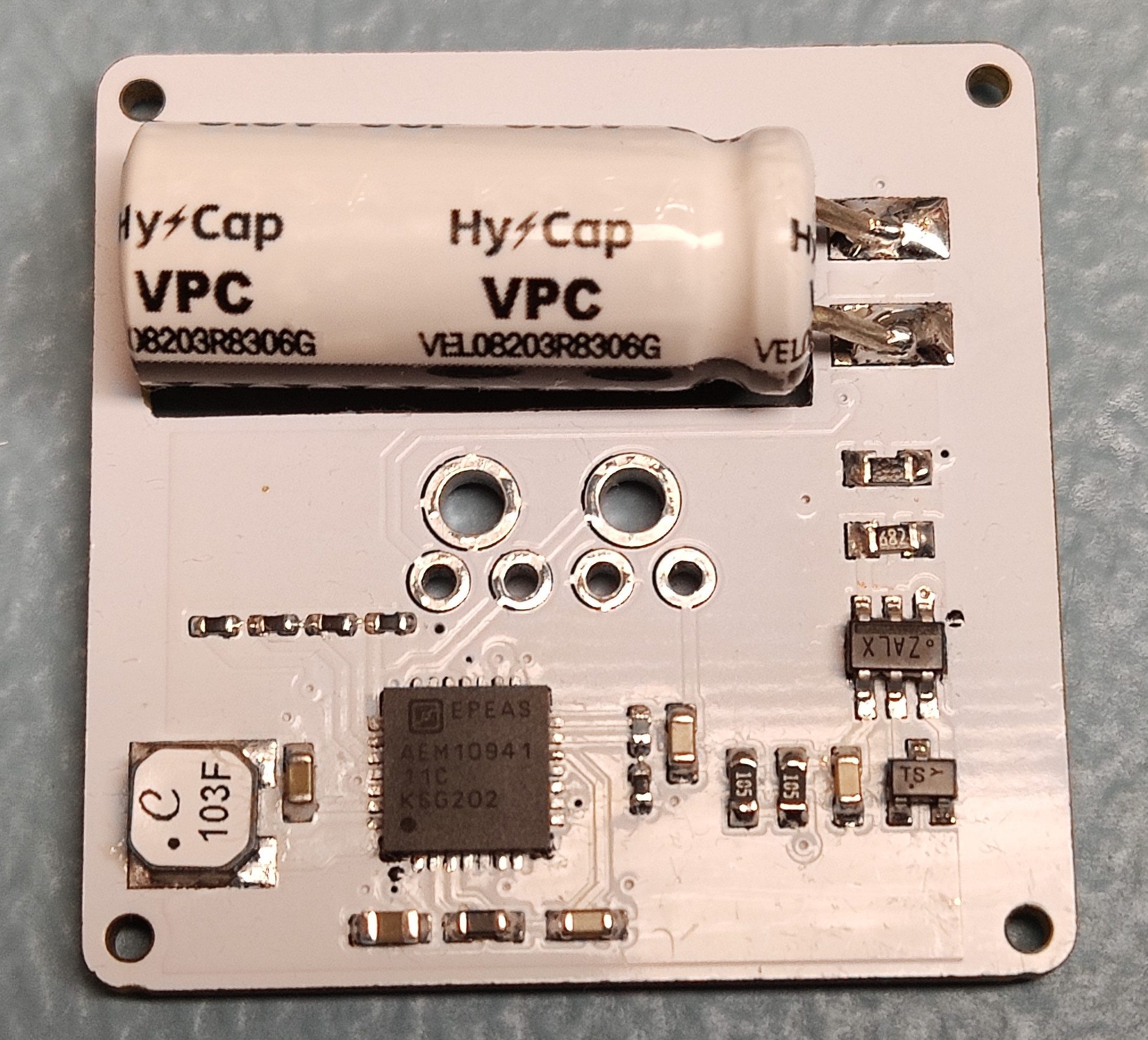
Small PCBA, large capacitor
What about that super capacitor? It’s called a Lithium Ion Capacitor (LIC) and is a hybrid between a typical rechargeable lithium battery and an electrolytic capacitor, offering extremely high capacity in a convenient two leg through hole form factor. This one is a whopping 30 Farad at 3.8 V, and we first saw it when [Jasper] won the Hackaday Earth Day contest last month. Check out that link if you want to know more about their uses and how to integrate them.
For more detail about all of the components of the solar pyramid we need only turn to the Hackaday archives. In December 2019 [Tom Nardi] wrote about building a cheap degassing system for making some very familiar looking resin pyramids. And before that [Donald Papp] brought us another familiar piece of the pyramid when he wrote up a different 1″ x 1″ solar harvesting system that [Jasper] designed.
Check out the video after the break to see what one of these gems looks like from all sides. And for many more experiments leading up the final pyramid check out the logs on the Hackaday.io page.