We see all kinds of projects come across the news desk at Hackaday. Sometimes it’s a bodge, neatly executed, that makes us laugh out loud at its simple ingenuity. Other times, it’s a case of great skill and attention to detail, brought to bear to craft something of great beauty. [Greg Davill]’s LED cube is firmly the latter.
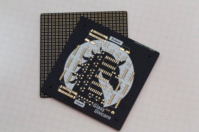
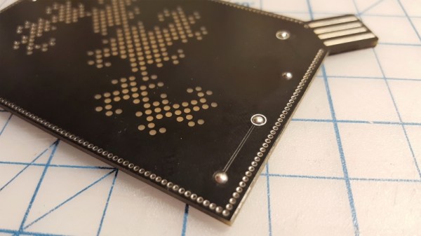
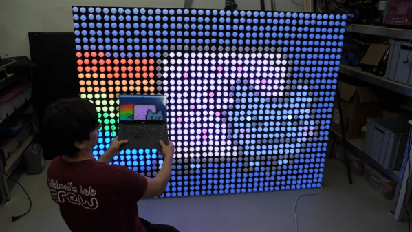
The build starts with custom four layer PCBs, in matte black with gold-plated pads. It’s a classic color scheme, and sets the bar for the rest of the project. Rather than proceeding to hook up some commodity microcontrollers to off-the-shelf panels, [Greg] goes his own way. Each PCB gets a 24×24 raw LED matrix, directly soldered on the back side. By producing a “dumb” matrix, there are large savings in current draw to be had over the now-popular smart strings.
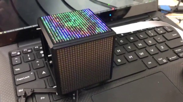
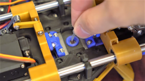
The panels are then loaded into a tidy 3D printed cube, with space inside for the FPGA running the show and a power supply. Five panels are held in with double sided-tape and screws, with the last being installed with magnets to allow access to the inside. Neatly folded flat-flex cables are pressed into service to connect everything up.
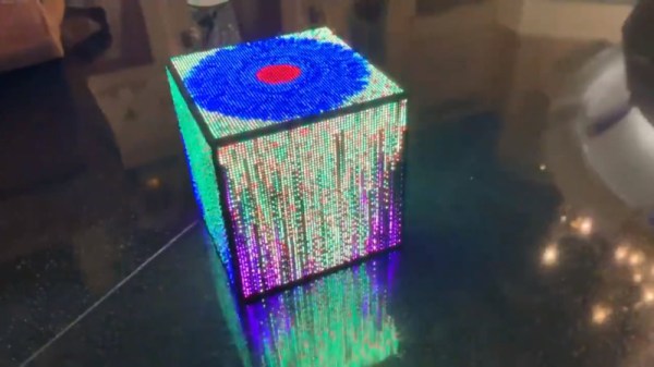
It’s a build that shows there is value in doing things your own way, and that the new methods don’t always beat out the old. With careful consideration of aesthetics from the start to the end of the project, [Greg] has built an LED cube both astounding in its simplicity, and beautiful in its execution. We’ve seen [Greg]’s work before, too – it’s not too often hand soldered BGAs cross these pages. Video after the break.
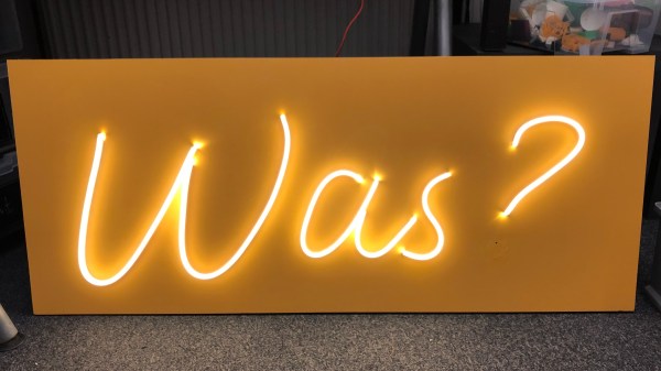
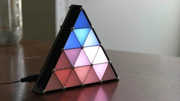
 Hailing from the recent past of 2014, it’s a design that is well-suited to the average makerspace. Built out of layers of lasercut chipboard and acrylic, it creates 16 seperate pockets for LEDs with very little bleed in between. A black bezel is fitted to complete the effect, along with frosted white acrylic diffusers for each triangle element.