Sometimes you don’t have the hardware you need, and you can either do without or let the project’s needs inspire you to create an alternative. That’s pretty sweet, and it’s even sweeter when you find a solution that’s dirt cheap.
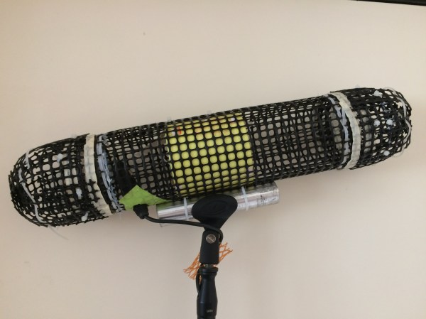
[Chu_st] created a sub-$10 blimp mount for his shotgun mike. It consists of a PVC pipe which attaches to the microphone’s shock mount. Plastic gardening grid is used for the shell, shaped by hand into the desired blimp shape and secured with zip ties and gaffer tape. [Chu_st] suggests using nylon stocking as a wind screen. The microphone itself attaches to a length of bicycle seat tube using a standard mic clamp.
We all know that speakers are microphones and microphones are speakers, right? If not, take a moment to plug your headphones into a microphone jack and yell into them. It’s not exactly hi-fi, but it works.
So it’s not a huge surprise that three security researchers in Israel have managed to turn the combination headphone and microphone input jacks that are present on most laptops into an eavesdropping device. (Paper here as PDF, with an obligatory demo video on YouTube, embedded below.) Speake(a)r is a neat proof-of-concept and a horrid pun. Continue reading “Eavesdropping Via Headphones”→
“Quick! We’re having a baby and we need a baby monitor!” Rather than run to the local big box and plunk down cash for an off-the-shelf solution, any self-respecting hacker would rise to the challenge and hit the shop to build something like this live streaming eye-in-the-sky baby camera. Right?
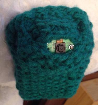
At least that’s how [Antibore] handled the situation, and the results are pretty good. He designed his build around an old Raspberry Pi 2 that was hanging around. That required a WiFi adapter, and since he wanted video and audio he needed a camera and mic. The first USB mic had a nice compact design but didn’t perform well, so a gutted gooseneck mic soldered right to the USB connector joined the design spec. A camera module, cell-phone quick charge battery bank, and a 3D printed case round out the BOM. A knitted cozy to keep it looking warm and fuzzy was provided by the mother-to-be — although we think it looks a little like [Mike Wazowski].
This self-contained unit will work anywhere it has access to a WiFi network. Mounted on the baby carrier, it’ll provide a live stream to any browser and provide the new parents with a little peace of mind.
There are a lot of baby monitors on the market, some of them terrible and in need of a rebuild. Kudos to [Antibore] for deciding to roll his own custom solution and for getting it done before the blessed event. Now how about painting that nursery?
Halloween has come and gone, but this DIY voice changing Star Wars Stormtrooper helmet tutorial by [Shawn Hymel] is worth a look for a number of reasons. Not only is the whole thing completely self-contained, but the voice changing is done in software thanks to the Teensy’s powerful audio filtering abilities. In addition, the Teensy also takes care of adding the iconic Stormtrooper clicks, pops, and static bursts around the voice-altered speech. Check out the video below to hear it in action.
Besides a microphone and speakers, there’s a Teensy 3.2, a low-cost add-on board for the Teensy that includes a small audio amp, a power supply… and that’s about it. There isn’t a separate WAV board or hacked MP3 player in sight.
[Matt] likes to make videos (and he’s pretty good at it judging by the quality of his videos). But video isn’t much without audio. Handheld recorders with small built-in microphones have a fairly high noise floor so [Matt] has a Rode NT1-A — a pricey but very quiet microphone. However, for field work, it isn’t handy since it requires a power supply and preamp to go along with it.
Another problem is that for stereo recording you need two and because they are quiet, they tend to pick up handling noise so you probably need to mount them on tripods. That’s all too much to carry around, especially on a hike. So [Matt] cannibalized two microphones. He repackaged them in a shock mount (made from a bird feeder and elastic), and added a battery pack and a custom preamp. The shock mount eliminates the handling noise and the custom PC boards mean you don’t have to carry a lot of extra gear.
The end result (see the video below) looks like someone made a purse out of a tribble, but it does sound good. If you hang on through most of the video (of fast forward to about 7:25), you can hear the microphones picking up thunderstorms, the ocean, the wind, and even [Matt’s] heartbeat.
A few years ago, [Artem] learned about ways to focus sound in an issue of Popular Mechanics. If sound can be focused, he reasoned, it could be focused onto a plane of microphones. Get enough microphones, and you have a ‘sound camera’, with each microphone a single pixel.
Movies and TV shows about comic books are now the height of culture, so a device using an array of microphones to produce an image isn’t an interesting demonstration of FFT, signal processing, and high-speed electronic design. It’s a Daredevil camera, and it’s one of the greatest builds we’ve ever seen.
[Artem]’s build log isn’t a step-by-step process on how to make a sound camera. Instead, he went through the entire process of building this array of microphones, and like all amazing builds the first step never works. The first prototype was based on a flatbed scanner camera, simply a flatbed scanner in a lightproof box with a pinhole. The idea was, by scanning a microphone back and forth, using the pinhole as a ‘lens’, [Artem] could detect where a sound was coming from. He pulled out his scanner, a signal generator, and ran the experiment. It didn’t work. The box was not soundproof, the inner chamber should have been anechoic, and even if it worked, this camera would only be able to produce an image or two a minute.
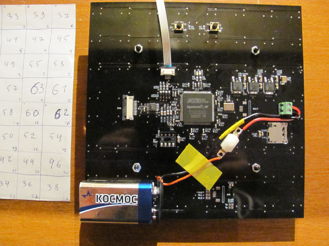
8×8 microphone array (mics on opposite side) connected to Altera FPGA at the center
The idea sat in the shelf of [Artem]’s mind for a while, and along the way he learned about FFT and how the gigantic Duga over the horizon radar actually worked. Math was the answer, and by using FFT to transform a microphones signals from up-and-down to buckets of frequency and intensity, he could build this camera.
That was the theory, anyway. Practicality has a way of getting in the way, and to build this gigantic sound camera he would need dozens of microphones, dozens of amplifiers, and a controller with enough analog pins, DACs, and processing power to make sense of all of this.
This complexity collapsed when [Artem] realized there was an off-the-shelf part that was a perfect microphone camera pixel. MEMS microphones, like the kind found in smartphones, take analog sound and turn it into a digital signal. Feed this into a fast enough microcontroller, and you can perform FFT on the signal and repeat the same process on the next pixel. This was the answer, and the only thing left to do was to build a board with an array of microphones.
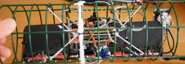
[Artem]’s camera microphone is constructed out of several modules, each of them consisting of an 8×8 array of MEMS microphones, controlled via FPGA. These individual modules can be chained together, and the ‘big build’ is a 32×32 array. After a few problems with manufacturing, the board actually worked. He was recording 64 channels of audio from a single panel. Turning on the FFT visualization and pointing it at a speaker revealed that yes, he had indeed made a sound camera.
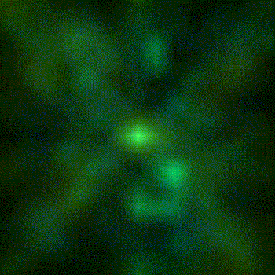
The result is a terribly crude movie with blobs of color, but that’s the reality of a camera that only has 32×32 resolution. Right now the sound camera works, the images are crude, and [Artem] has a few ideas of where to go next. A cheap PC is fast enough to record and process all the data, but now it’s an issue of bandwidth; 30 sounds per second is a total of 64 Mbps of data. That’s doable, but it would need another FPGA implementation.
Is this sonic vision? Yes, technically the board works. No, in that the project is stalled, and it’s expensive by any electronic hobbyist standards. Still, it’s one of the best to grace our front page.
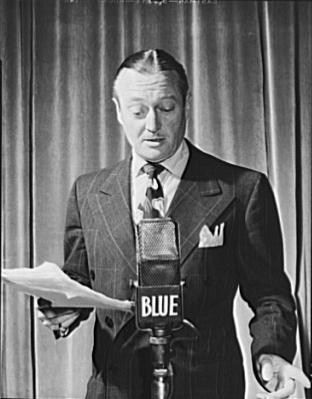
If you’ve ever seen an old movie or TV show where there was a radio announcer, you’ve probably seen a ribbon microphone. The RCA 44 (see Edmund Lowe, on right) had exceptional sound quality and are still valued today in certain applications. The name ribbon microphone is because the sound pickup is literally a thin strip of aluminum or other conductive material.
Unlike other common microphones, ribbons pick up high frequencies much better due to the high resonant frequency of the metallic ribbon. This is not only better in general, but it means the ribbon mic has a flatter frequency response even at lower frequencies. Another unique feature is that the microphone is bidirectional, hearing sounds from the front or back equally well. It is possible to build them with other directional patterns, although you rarely see that in practice.
Invention
In the early 1920s, Walter Schottky and Erwin Gerlach developed the ribbon microphone (and, coincidentally, the first ribbon loudspeaker). Harry Olson at RCA developed a ribbon mic that used coils and permanent magnets which led to the RCA Photophone Type PB-31 in 1931. Because of their superior audio response, they were instant hits and Radio City Music Hall started using the PB-31 in 1932. A newer version appeared in 1933, the 44A, which reduced reverberation.

 At least that’s how [Antibore] handled the situation, and the results are pretty good. He designed his build around an old Raspberry Pi 2 that was hanging around. That required a WiFi adapter, and since he wanted video and audio he needed a camera and mic. The first USB mic had a nice compact design but didn’t perform well, so a gutted gooseneck mic soldered right to the USB connector joined the design spec. A camera module, cell-phone quick charge battery bank, and a 3D printed case round out the BOM. A knitted cozy to keep it looking warm and fuzzy was provided by the mother-to-be — although we think it
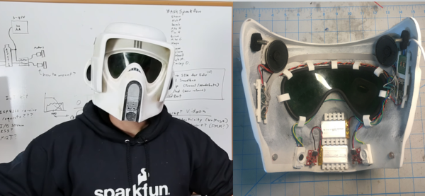
 Another problem is that for stereo recording you need two and because they are quiet, they tend to pick up handling noise so you probably need to mount them on tripods. That’s all too much to carry around, especially on a hike. So [Matt]
 [Artem]’s camera microphone is constructed out of several modules, each of them consisting of an 8×8 array of MEMS microphones, controlled via FPGA. These individual modules can be chained together, and the ‘big build’ is a 32×32 array. After a few problems with manufacturing, the board actually worked. He was recording 64 channels of audio from a single panel. Turning on the FFT visualization and pointing it at a speaker revealed that yes, he had indeed made a sound camera.