Reading Data From A CD, With A Microscope

There was a time when electronic engineering students studied the audio CD, for all its real-world examples of error correction and control systems. There’s something to be found in the system still for young and old though, and thus we were intrigued when we saw [Peter Monta] reading the data from a CD using a microscope.

CDs encode data as so-called pits and lands in a spiral track across a metalised surface, with a transition from pit to land signifying a logic 1 and a missing transition signifying a 0. Reading a section of the raw data is achieved in the first part of his write-up, but in the next installment he goes further into retrieving more data through stitching together microscope pictures and writing some code to retrieve data frames. He’s not quite at the audio playback stage, but he’s planning in the future to spiral-track a full image to rip an entire disc.

There are plenty of CD drives around to read audio the conventional way, but the techniques here still find a use where less ubiquitous media has to be read. In the last decade for example there was an effort to read the BBC Domesday Project from the 1980s, as it became clear that few of the original readers survived in working order.

Laser Scanning Microscope Built With Blu-ray Parts

Laser scanning microscopes are useful for all kinds of tiny investigations. As it turns out, you can build one using parts salvaged from a Blu-ray player, as demonstrated by [Doctor Volt].

The trick is repurposing the optical pickup unit that is typically used to read optical discs. In particular, the build relies on the photodiodes that are usually used to compute focus error when tracking a disc. To turn this into a laser scanning microscope, the optical pickup is fitted to a 3D printed assembly that can slew it linearly for imaging purposes.

Meanwhile, the Blu-ray player’s hardware is repurposed to create a sample tray that slews on the orthogonal axis for full X-Y control. An ESP32 is then charged with running motion control and the laser. It also captures signals from the photodiodes and sends them to a computer for collation and display.

[Doctor Volt] demonstrates the microscope by imaging a small fabric fragment. The scanned area covers less than 1 mm x 1 mm, with a resolution of 127 x 127, though this could be improved with finer pitch on the slew mechanisms.

While it’s hardly what we’d call a beginner’s project, this technique still looks a lot more approachable than building your own scanning electron microscope.

Continue reading “Laser Scanning Microscope Built With Blu-ray Parts”

DIY Comparatron Helps Trace Tiny, Complex Objects

Hackers frequently find themselves reverse-engineering or interfacing to existing hardware and devices, and when that interface needs to be a physical one, it really pays to be able to take accurate measurements.

This is easy to do when an object is big enough to fit inside calipers, or at least straight enough to be laid against a ruler. But what does one do when things are complex shapes, or especially small? That’s where [Cameron]’s DIY digital optical comparator comes in, and unlike commercial units it’s entirely within the reach (and budget) of a clever hacker.

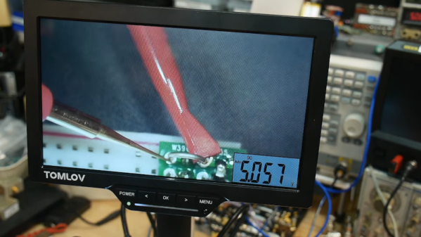
The Comparatron is based off a CNC pen plotter, but instead of a pen, it has a USB microscope attached with the help of a 3D-printed fixture. Serving as a background is an LED-illuminated panel, the kind useful for tracing. The physical build instructions are here, but the image should give most mechanically-minded folks a pretty clear idea of how it fits together.

Continue reading “DIY Comparatron Helps Trace Tiny, Complex Objects”

DVD Drives Turned Into Microscopes

With the advent of streaming services, plenty of people are opting to forego the collection of physical media. In turn, there are now a lot of optical drives sitting unused in parts bins and old computers. If you’d like something useful to do with this now-obsolete technology, you can have a try at turning one into a laser microscope.

This build requires two DVD pickups. By scanning once horizontally and once vertically and measuring the returning light from the DVD laser, an image can be created. For this build, the second pickup is used to move the object itself. The entire device is controlled by an Analog Discovery 2, although this principle could be ported to other microcontroller platforms. Thanks to the extremely fine laser in a DVD and the precise movements of the motors found in the control machinery, the images obtained using this method have the potential to be more detailed than comparable visible light microscopes.

While this isn’t quite scanning electron microscope territory, it’s good enough to clearly image the internal workings of a de-capped integrated circuit. Something like this could be indispensable for reverse-engineering ICs or troubleshooting other comparably small electronics, with resolutions higher than can typically be obtained with visible light microscopes. We’ve even seen similar builds in the past which build microscopes like this as dedicated lab equipment.

Trying Out A 3D Printed Microscope Lens Adapter

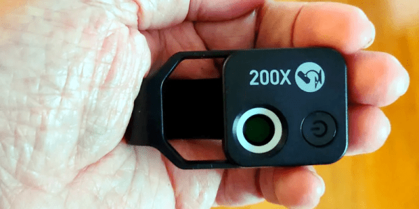
If you want to take pictures of tiny things close up, you need a macro lens. Or a microscope. [Nicholas Sherlock] thought “Why not both?” He designed a 3D-printed microscope lens adapter that you can find on Thingiverse. Recently, [Micael Widell] tried it out with a microscope lens and you can see the results in the video below.

A $20 microscope lens allows for some amazing shots. There are two designs that fit different cropped-image and full-frame cameras. As you might expect, the depth of field is razor-thin, probably sub-millimeter. Additionally, with a 4X lens on a 35 mm sensor, the field of view is about 9 mm so you have to have a steady hand just to keep everything in frame.

Continue reading “Trying Out A 3D Printed Microscope Lens Adapter”

How Small Is Too Small?

Not a rhetorical question! This week we consider the most micro microcontroller: the HC32L110. It’s the new title holder of the smallest ARM Cortex M0+ part. But could you actually use it?

MCU is the black thing that’s smaller than the capacitor.

I remember way back, when I first learned to solder surface-mount components. It was fiddly at first, but nowadays I don’t use through-hole components unless someone’s twisting my arm. And I still do my soldering myself — down to 0603 really isn’t all that bad with an iron, and below that, there’s always the heat plate. My heat plate has also gotten me through the two times I’ve actually needed to put down a ball-grid-array part. It wasn’t as bad as I had feared, honestly.

So maybe it’s time for me to take the BGA plunge and design a board or two just to get more familiar with the tech. I probably won’t dive straight into the deep end, like the featured chip here with 0.35 mm ball pitch, but rather stick with something that the cheap PCB services can easily handle. My experience tells me that the best way to learn something is just to test it out.

Now, off to go part shopping in the middle of a chip crisis! Wish me luck.

555 Teardown Isn’t Just A Good Time, It’s To Die For

It seems only appropriate that hot on the heels of the conclusion of Hackaday’s 555 Timer Contest that [Ken Shirriff] posts a silicon die teardown of an early version of a hacker’s favorite chip, the 555.

A Microscopic View Of the 555 Die

Starting with a mystery chip from January 1973, [Eric Schlaepfer] painstakingly sanded down the package to reveal the die, which he deemed to be a 555 timer. Why didn’t they know it was a 555 timer to start? Because the package was not marked with “555” but rather some other marks that you can see in the blog post.

In addition to a great explanation of how the 555 works in general, [Ken] has taken a microscopic look at the 555 die itself. The schematic of a 555 is easily available, and [Ken] identifies not just sections of the die but individual components. He goes further yet by explaining how the PNP and NPN resistors are constructed in silicon. There’s also a nice and juicy bit of insight into the resistors in the IC, but we won’t spoil it here.

Be sure to show your love for the winners of the 555 contest, or at the very least check out the project that took the stop spot: a giant sized 555 that you don’t need a microscope to see inside of.