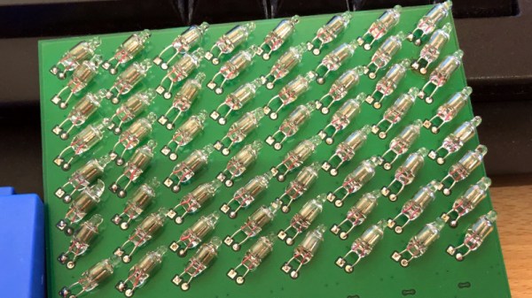
Powering Neon With A Joule Thief

Joule thief are small, fun circuits which exploit a few characteristics of electronics and LEDs in order to “steal” virtually all of the energy stored in a battery. They can operate at incredibly small voltages and are fairly simple to make. With a few modifications to this basic circuit it’s possible to drive other things than an LED, though, like this joule thief that lights up a neon bulb.

The circuit from [suedbunker] aka [fuselage] is based on a pin from the Chaos Communication Camp which had a standard LED. To get a neon light to illuminate a few modifications to the standard joule thief are needed.

First, the windings have to be changed from 10:10 to 10:80 to increase the voltage across the bulb. Second, a transistor with slightly different characteristics was used than the original design. The capacitor was also replaced with a larger one.

While it might seem simple, the physics of how a joule thief works are anything but, and modifying the delicate circuit to work with something other than an LED is commendable. It also has a steampunk vibe which is a cool look even in projects that don’t involve steam at all.

Visualizing Energy Fields With A Neon Bulb Array

Everyone knows that one of the coolest things to do with a Tesla coil is to light up neon or fluorescent tubes at a distance. It’s an easy and very visual way to conceptualize how much energy is being pumped out, making it a favorite trick at science museums all over the world. But what would it look like if you took that same concept and increased the resolution? Replace that single large tube with an array of smaller ones. That’s exactly what [Jay Bowles] did in his latest video, and the results are impressive to say the least.

From a hardware standpoint, it doesn’t get much simpler. [Jay] knew from experience that if you bring a small neon indicator close to a Tesla coil, it will start to glow when approximately 80 volts is going through it. The higher the voltage, the brighter the glow. So he took 100 of these little neon bulbs and arranged them in a 10×10 grid on a piece of perfboard. There’s nothing fancy around the backside either, just all the legs wired up in parallel.

When [Jay] brings the device close to his various high-voltage toys, the neon bulbs still glow like they did before. But the trick is, they don’t all glow at the same brightness or time. As the panel is moved around, the user can actually see the shape and relative strength of the field by looking at the “picture” created by the neon bulbs.

The device isn’t just a cool visual either, it has legitimate applications. In the video, [Jay] explains how it allowed him to observe an anomalous energy field that collapsed when he touched the base of his recently completed Tesla coil; an indication that there was a grounding issue. He’s also observed some dead spots while using what he’s come to call his “High-Voltage Lite-Bright” and is interested in hearing possible explanations for what he’s seeing.

We’ve been fans of [Jay] and the impressively produced videos he makes about his high-voltage projects for years now, and we’re always excited when he’s got something new. Most hardware hackers start getting sweaty palms once the meter starts indicating more than about 24 VDC, so we’ve got a lot of respect for anyone who can build this kind of hardware and effectively communicate how it works to others.

Continue reading “Visualizing Energy Fields With A Neon Bulb Array”

Custom Nixies Perform When Cranked Up To 100,000 Hertz

With the popularity of Nixie clocks, we’d be forgiven for thinking that the glowing tubes are only good for applications with a stately pace of change. But we forget that before they became the must-have hobbyist accessory, Nixies were used in all kinds of scientific instruments, from frequency counters to precision multimeters. In such applications, update rates in the hundreds or thousands of Hertz aren’t uncommon, and the humble Nixie handled display refreshes with ease.

But what about refreshing a Nixie at 100 kHz? That was the question put to artisanal Nixie maker [Dalibor Farný] by a client who wanted a timer to calibrate high-speed cameras. It was a feat that [Dalibor] wasn’t sure his custom-made tubes could handle. The video below shows his efforts to find out.

If you ever wanted to know about the physics of gas-discharge displays like the Nixie, the fifteen minutes starting at about 5:13 will give you everything you need. That basic problem boils down to the half-life of excited neon, or how long it takes for half the population of excited molecules to return to the ground state. That, in turn, dictates how long a given cathode will continue to visibly glow after it’s turned off, which determines how many digits will appear illuminated at once.

To answer that, they engaged a company in Prague with a camera capable of a mind-blowing 900,000 frames per second. Even though they found a significant afterglow period for each cathode, even at 100 kHz it’s clear which digit is the one that’s currently illuminated. They also looked at the startup of digits in a cold Nixie versus one that’s warmed up, leading to some fascinating footage at around 26:30.

We appreciate [Dalibor]’s attention to detail, not only in the craftsmanship of his custom tubes but in making sure they’re going to do their job. He recently did a failure analysis on some of his high-end clocks that showed the same care for his product and his brand.

Continue reading “Custom Nixies Perform When Cranked Up To 100,000 Hertz”

Multimeter Display Perked Up With Nixies, LEDs, And Neon Tubes

Just because something is newer than something else doesn’t automatically make it better. Of course the opposite is also true, but when it comes to displays on bench multimeters, a fancy LCD display is no guarantee of legibility. Take the Hewlett Packard HP 3478A multimeter; the stock transflective display with its 14-segment characters is so hard to read that people usually have to add a backlight to use it.

That wasn’t good enough for [cyclotronboy], though, who chose to completely replace the stock 3478A display with Nixie tubes. He noticed that with a little modification, six IN-17 tubes just fit in the window vacated by the LCD. He sniffed out the serial data stream going to the display with a collection of XOR gates and flip-flops, which let him write the code for a PIC18F4550. The finished display adds a trio of rectangular LEDs for the + and – indicators, and an HDLO-1414 four-character alphanumeric display to indicate units and the like. And the decimal points? Tiny neon bulbs. It already looks miles better than the stock display, and with the addition of a red filter, it should look even better.

If you’re stuck with a lame LCD multimeter but Nixies don’t quite do it for you, worry not – an LED conversion is possible too.

MIDI Controlled Neon

The people who make neon signs are a vibrant community with glass bending and high voltage electronics. There is a need, though, to sequence these neon signs, and it seems like MIDI is the way to do it. That’s what [david] is doing for his entry to the Hackaday Prize, and the results already look great.

The idea for this project is to transmit MIDI data to a controller that activates neon tubes accordingly. As for why [david] chose MIDI over DMX512 or some other protocol, the object here is to sync with music, and if you already have a drum machine sending MIDI out, you might as well just patch into that.

The build uses an Arduino Leonardo with a MIDI shield produced by Olimex. This shield is connected to a neon power supply that has control circuitry to quickly and easily turn neon signs on and off. The end result is a laptop (with the rest of the DJ software) sending a MIDI clock signal to an Akai drum machine. This drum machine outputs MIDI notes to the shield, which is currently set up to control three neon transformers.

The results look great, with flashing skulls synchronized with bleeps and bloops. This, of course, can be expanded to even more MIDI synced neon signs. You can check out a few videos of the build after the break.

Continue reading “MIDI Controlled Neon”

Pocket High Voltage Generator Becomes Great Test Tool

[The LED Artist] often found a need for a relatively high voltage (100 to 200 Volt) but low current DC power supply, and it turns out that a small HV generator that uses a single AA cell only took about an hour to make. The device ended up being a pretty handy tool for testing things like LED filaments (which have a forward voltage of over 60 V), or even neon and nixie tubes.

The device’s low current means that nixie and neon elements won’t light up very brightly, but they will light up enough to verify function and operation. [The LED Artist] reports that touching the output terminals of the generator only causes a slight tingling sensation.

Open-circuit voltage generated from a single AA cell is about 200 V, but that voltage drops rapidly under any kind of load. Even regular LEDs can be safely lit with the circuit, with less than a milliamp being supplied at the two to three volts at which most regular LEDs operate.

[The LED Artist] fit the device into a two-AA battery holder, with a single AA cell on one side and the circuit in the other, and says it’s one of the more useful tools they’ve ever made. LED filaments are fairly common nowadays, but if they intrigue you, don’t forget that [Mike Harrison] covered everything you need to know about experimenting with them.

Neon Lamps Make For The Coolest Of Nixie Clocks

Revisiting old projects is always fun and this Nixie Clock by [pa3fwm] is just a classic. Instead of using transistors or microcontrollers, it uses neon lamps to clock and drive the Nixie Displays. The neon lamps themselves are the logic elements. Seriously, this masterpiece just oozes geekiness.

Inspired by the book “Electronic Counting Circuits” by J.B. Dance(ZIP), published in 1967, we covered the initial build a few years back. The fundamental concept of operation is similar to that of Neon Ring Counters. [Luc Small] has a write-up explaining the construction of such a device and some math associated with it. In this project, [pa3fwm] uses modern day neons that you find in indicators, so his circuit is also updated to compensate for the smaller difference in striking and maintaining voltages.

The original project was done in 2007 and has since undergone a few upgrades. [Pa3fwm] has modified the construction to make it wall mounted. Even though it’s not a precise timekeeper, the project itself is a keeper from its time. Check out the video below for a demonstration.

Feel inspired yet? Take a peek at the White Rabbit Nixie Clock and you are looking for a low voltage solution to powering Nixies then check out the 5-volt Nixie Power supply.

Continue reading “Neon Lamps Make For The Coolest Of Nixie Clocks”