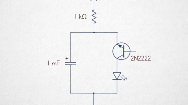
It’s Hard To Make A (Good) Oscillator

There’s more to making an oscillator than meets the eye, and [lcamtuf] is here with a good primer on the subject. It starts with the old joke that if you need an oscillator it’s best to try to make an amplifier instead, but of course the real point here is to learn how to make not just a mere oscillator, but a good oscillator.

He does this by taking the oscillator back to first principles and explaining positive feedback on an amplifier, before introducing the Schmitt trigger, an RC circuit to induce a delay, and then phase shift. These oscillators are not complex circuits by any means, so understanding their principles should allow you to unlock the secrets of oscillation in a less haphazard way than just plugging in values and hoping.

Oscillation is a subject we’ve taken a deep dive into ourselves here at Hackaday, should you wish to learn any more. Meanshile [lcamtuf] is someone we’ve heard from here before, with a comparative review of inexpensive printed circuit board manufacturers.

Candle Oscillator Really Heats Things Up

As the timebase for a clock, almost anything with a periodic oscillation can be used. Traditionally, that meant a pendulum, but in our time, we’ve seen plenty of others. Perhaps none as unusual as [Tim]’s candle flicker clock, though.

Candles are known for their flickering, a property of the wick and the fuel supply that candle manufacturers have gone to great lengths to mitigate. If you bring several of them together, they will have a significant flicker, with a surprisingly consistent 9.9 Hz frequency. This is the timebase for the clock, with the capacitance of the flame being sensed by a wire connected to a CH32 microcontroller, and processed to produce the required timing.

We like this project, and consider it a shame that it’s not an entry in our One Hertz Challenge.  Oddly, though, it’s not the first candle-based oscillator we’ve seen; they can even be turned into active electronic devices.

On the left side of the image, three lit candles are positioned next to each other, so that the flames merge. On the right side, an oscilloscope screen is shown displaying an oscillating waveform.

2025 One Hertz Challenge: A Flaming Oscillator And A New Take On The Candle Clock

Candle clocks were once an easy way to build a clock without using complex mechanical devices: just observe how quickly a thin candle burns down, mark an identical candle with periodic gradations, and you had a simple timer. These were the first candle-based timekeeping devices, but as [Tim]’s flicker-based oscillator demonstrates, they’re certainly not the only way to keep time with a flame.

Generally speaking, modern candles minimize flickering by using a wick that’s designed to balance the amount of wax and air drawn into the flame. However, when several candles are brought close together, their flames begin to interfere with each other, causing them to flicker in synchrony. The frequency of flickering is a function of gravity and flame diameter alone, so a bundle of three candles will flicker at a fairly constant frequency; in [Tim]’s case, it was about 9.9 Hz.

To sense this oscillation, [Tim] originally used a phototransistor to detect the flame’s light, but he wanted an even simpler solution. He positioned a wire just above the flame, so that as it flickered it would periodically contact the wire. A flame has a different dielectric constant than air does, so the capacitance between this and another wire wrapped around the bundle of candles fluctuates with the flame. To sense this, he used a CH32V003 microcontroller, which reads capacitance, performs some signal processing to get a clean signal, counts oscillations, and uses this time signal to blink an LED once a second. The final result is unusually mesmerizing for a blinking LED.

In something of the reverse of this project, we’ve also seen an oscillator used for an (artificial) candle. There’s also a surprising amount of science that can be learned by studying candles.

Continue reading “2025 One Hertz Challenge: A Flaming Oscillator And A New Take On The Candle Clock”

A sine wave and triangle wave on a black background

2025 One Hertz Challenge: Op-Amp Madness

Sometimes, there are too many choices in this world. My benchtop function generator can output a sine, square, or saw wave anywhere from 0.01 Hz up to 60 MHz? Way too many choices. At least, that’s what we suspect [Phil Weasel] was thinking when he built this Analog 1 Hz Sinewave Generator.

Rendering of a PCB
A KiCad rendering of [Phil]’s design
[Phil]’s AWG (which in this case stands for Anything as long as it’s a 1 Hz sine Wave Generator) has another unique feature — it’s built (almost) entirely with op-amps. A lot of op-amps (37, by our count of the initial schematic he posted). His design is similar to a Phased Locked Loop (PLL) and boils down to a triangle wave oscillator. While a 1 Hz triangle wave would absolutely satisfy judges of the One Hertz Challenge, [Phil] had set out to make a sine wave. Using a feedback loop and some shaping/smoothing tricks (and more op-amps), he rounded off the sharp peaks into a nice smooth sine wave.

Sometimes we make things much more complicated than we need to, just to see if we can. This is one of those times. Are there much simpler ways to generate a sine wave? Yes — but not exclusively using op-amps! This entry brings stiff competition to the “Ridiculous” category of the 2025 One Hertz Challenge.

Oscillator Negativity Is A Good Thing

Many people who get analog electronics still struggle a bit to design oscillators. Even common simulators often need a trick to simulate some oscillating circuits. The Barkhausen criteria state that for stable oscillation, the loop gain must be one, and the phase shift around the feedback loop must be a multiple of 360 degrees. [All Electronics Channel] provides a thorough exploration of oscillators and, specifically, negative resistance, which is punctuated by practical measurements using a VNA. Check it out in the video below.

The video does have a little math and even mentions differential equations, but don’t worry. He points out that the universe solves the equation for you.

In an LC circuit, you can consider the losses in the circuit as a resistor. That makes sense. No component is perfect. But if you could provide a negative resistance, it would cancel out the parasitic resistance. With no loss, the inductor and capacitor will go back and forth, electrically, much like a pendulum.

So, how do you get a negative resistance? You’ll need an active device. He presents some example oscillator architectures and explains how they generate negative resistances.

Crystals are a great thing to look at with a VNA. That used to be a high-dollar piece of test gear, but not anymore.

Continue reading “Oscillator Negativity Is A Good Thing”

Recreating The Analog Beauty Of A Vintage Tektronix Oscillator

Tektronix must have been quite a place to work back in the 1980s. The company offered a bewildering selection of test equipment, and while the digital age was creeping in, much of their gear was still firmly rooted in the analog world. And some of the engineering tricks the Tek wizards pulled off are still the stuff of legend.

One such gem of analog design was the SG505, an ultra-low-distortion oscillator module that [Paul] is trying to replicate with modern parts. That’s a tall order since not only did the original specs on this oscillator call for less than 0.0008% total harmonic distortion over a frequency range of 20 Hz to 20 kHz, but a lot of the components it used are no longer manufactured. Tek also tended to use a lot of custom parts, especially mechanical ones like the barrel switch used to select attenuation levels in the SG505, leaving [Paul] no choice but to engineer his way around them.

So far, [Paul] has managed to track down most of the critical components or source suitable substitutes. One major win was locating the original J-FET Tek used in the oscillator’s AGC circuit. One part that’s proven more elusive is the potentiometer that Tek used to adjust the frequency; who knew that finding a dual-gang precision wirewound 10k single-turn pot with no physical stop would be such a chore?

[Paul] still seems to be very much in the planning stages of this project yet, and that’s probably for the best since projects such as these live and die on proper planning. We’re keen to see how this develops, and we’re very much looking forward to seeing the FFT results. We also imagine he’ll be busting out his custom curve tracer at some point in the build, too.

VNAs And Crystals

Oscillators may use crystals as precise tuned circuits. If you have a vector network analyzer (VNA) — or even some basic test equipment — you can use it to learn the parameters of a crystal. [All Electronics Channel] has the details, and you can see how in the video below.

There was a time when a VNA was an exotic piece of gear, but these days they are relatively common. Crystal parameters are important because crystals have a series resonance and a parallel resonance and they are not at the same frequency. You also may need to know how much loading capacitance you have to supply to get the crystal at the right frequency.

Sometimes, you want to pull the crystal frequency, and the parameters will help you figure that out, too. It can also help if you have a crystal specified as series in a parallel-mode oscillator or vice versa.

If you don’t have a VNA, you can use a tracking signal generator, as [Grégory] shows towards the middle of the video. The quality of a tuned circuit depends on the Q factor, and crystals have a very high Q factor.

We did something similar in 2018. The other way to pull a crystal frequency is a bit extreme.

Continue reading “VNAs And Crystals”