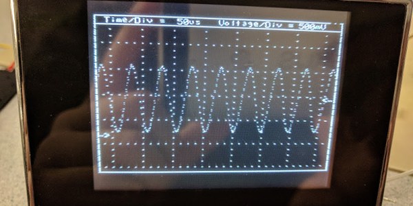
When troubleshooting circuits it’s handy to have an oscilloscope around, but often we aren’t in a lab setting with all of our fancy, expensive tools at our disposal. Luckily the price of some basic oscilloscopes has dropped considerably in the past several years, but if you want to roll out your own solution to the “portable oscilloscope” problem the electrical engineering students at Cornell produced an oscilloscope that only needs a few knobs, a PIC, and a small TV.
[Junpeng] and [Kevin] are taking their design class, and built this prototype to be inexpensive and portable while still maintaining a high sample rate and preserving all of the core functions of a traditional oscilloscope. The scope can function anywhere under 100 kHz, and outputs NTSC at 30 frames per second. The user can control the ground level, the voltage and time scales, and a trigger. The oscilloscope has one channel, but this could be expanded easily enough if it isn’t sufficient for a real field application.
All in all, this is a great demonstration of what you can accomplish with a microcontroller and (almost) an engineering degree. To that end, the students go into an incredible amount of detail about how the oscilloscope works since this is a design class. About twice a year we see a lot of these projects popping up, and it’s always interesting to see the new challenges facing students in these classes.
What do a Rogowski coil, a magnetic core, and a hall effect sensor have in common? They are all ways you can make oscilloscope probes that measure current. If you think of a scope as a voltage measurement device, you ought to watch the recent video from Keysight Technology (see below). It is true that Keysight would love to sell you a probe, but the video is not a sales pitch, just general technical information about making current measurements with an oscilloscope.
Of course, you can always measure the voltage across a shunt resistor — either one that is naturally in the circuit or one you’ve put inline just for measuring purposes. But if you add a resistor it will change the circuit subtly and it may have to handle a lot of power.
The Keysight video points out that there are different probes for different current measurement regimes. High current, medium current, and low current all use different probes with different technologies. The video is only about 6 minutes long and if you’ve never thought about measuring current with a scope, it is worth watching.
The video shares some high-level details of how the current probes work — that’s where the Rogowski coil comes in, for example. Of course, you can’t expect a vendor to tell you how to build your own current probes. That’s OK, though, because we will. Current probes are often expensive, but you can sometimes pick up a deal on a used one.
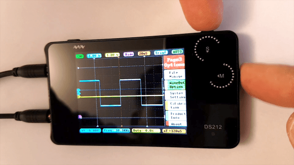
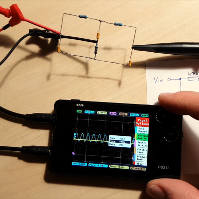
We’ve seen plenty of oscilloscopes that look like repurposed cell phones. Usually, though, they only have one channel. The DS212, has two channels and a signal generator! [Marco] gives his review and a quick tear down in the video below.
The scope isn’t going to replace a big bench instrument, but for a portable scope with a rechargeable battery, it isn’t bad. The 1 MHz analog bandwidth combines with a 10 megasample per second front end and 8K of sample memory. The signal generator can produce basic waveforms up to 1 MHz. We were somewhat surprised the unit didn’t sport a touch screen, which is why you can see [Marco’s] fingers in the screenshot above. He seems to like the dual rotary encoder system the devices uses for navigation.
Where this really stands out is that it is open source for the the firmware running on the STM32 processor inside. We so rarely see this for commercially available bench tools and it makes this a fine hacking platform. It’s easy to imagine adding features like digital signals out and decoding digital data. It would be interesting to marry it with a WiFi chip and use it as a front end for another device over WiFi. Lots of possibilities. [Marco] shows that even though he’s not familiar with the STM32, he was able to add a custom waveform output to the device easily. This has the potential to be a custom troubleshooting platform for your builds. Lining up all of the sensing and signal generation settings for each specific type of test means you don’t need a guru to walk through the common failure modes of a product.
There are many small inexpensive scopes out there that might not match a big bench instrument but can still be plenty useful. [Jenny List] just reviewed one that comes in at around $21. And last year, we saw a sub-$100 scope that would net you just one channel scope. That’s progress!
When men were men, and oscilloscopes were oscillographs.
Do you remember your first oscilloscope? Maybe we have entered the era in which younger readers think of a sleek model with an LCD screen, but for the slightly older among us the image that will come to mind is likely to be a CRT-based behemoth. Mine was a 2MHz bandwidth Cossor from the 1950s, wildly outdated by the 1980s, but it came to me at no cost. It proudly proclaims itself as a “Portable Oscillograph”, but requires its owner to be a weightlifter to move it. I still have it, as a relic and curio.
For most of us a new ‘scope is still a significant investment. Even affordable current models such as the extremely popular Rigol instruments are likely to cost several hundred dollars, but offer measurement functions undreamed of by those 1950s engineers who would have looked on the Cossor as an object of desire.
Oscilloscope buyers on a budget may not have the cash for a Rigol, a Hantek, or any of the other affordable ‘scopes. Someone starting on the road of electronic engineering can scout around for a cheap or free second-hand CRT model, but thanks to the ever advancing march of technology they also have another option. Modern microprocessors and microcontrollers have analogue-to-digital converters and processor cores that are fast enough to provide the functions of a simple oscilloscope, and to that end a variety of very cheap ‘scopes and ‘scope kits have come on the market. These invariably have a rather small LCD screen and a relatively low bandwidth, but since they can be had for almost pocket-money prices their shortcomings can be overlooked in the name of value. It’s been a matter of curiosity for some time then: are these instruments any good? For around £16 ($21) and the minor effort of an online order from China, we decided to find out.
If you look at most stockists of electronic kits these days, you are likely to find an oscilloscope kit in their range. These are volume produced in China, and the same design trends appear across different models. You can buy surface mount or through-hole, and most of them feature a bare board with maybe a piece of laser-cut Perspex standing in for a case. There are one or two models appearing that come with a case though, and it was one of these that we ordered. The JYE Tech DSO150 is a single-channel ‘scope with a 2.4″ 320×240 pixel colour LCD screen and a 200kHz bandwidth. Its specification is typical of the crop of similar kits, though its smart case sets it apart and made it an easy choice.
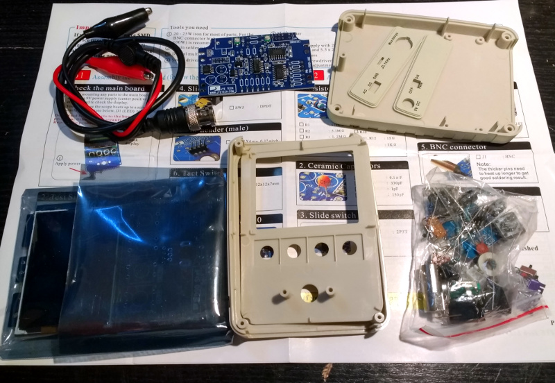
In the Box
We ordered one, and when it arrived, it was packed in a small cardboard carton that had suffered some crushing in transit, but had protected the internal contents well enough that no harm had been done. A layer of foam protected the LCD, and the case parts appeared rigid enough to protect the rest of the components. There was a bag of discretes, the case parts, two PCBs, a test lead with crocodile clips, and two pages of instructions.
When looking at a kit, it’s best to start with the instructions, because no matter the quality of the kit itself it is the quality of the instructions that make or break a kit. If you can’t build it then it doesn’t matter how good it might be, it’s effectively junk.
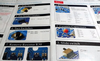
The DSO150 instructions are two sheets of high quality double-sided colour print, with the emphasis on pictures rather than words, The front page introduces the kit and gives a quick soldering guide, then the next two pages step through each stage of construction. The final page has basic instructions for use, specification, and a troubleshooting guide. Our kit had all surface-mount parts already fitted, if we’d known the kit could also be had with SMD parts to fit we’d have bought that version instead.
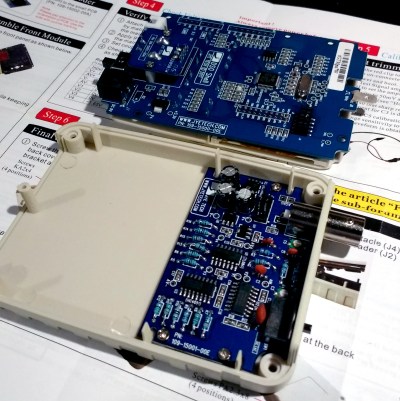
Inside the DSO100.
The instruction steps are long on images and short on text, but there are sometimes few cues as to where the component in question lies on the board. Sometimes some careful examination of board and picture is necessary to ensure correct placement. The first step though doesn’t involve any soldering, wire the main board up to a 9V supply, and watch the LCD boot into the oscilloscope software. There is support via a forum on the JYE Tech website, we presume you’d go there if it failed to boot out of the box. A 9V PSU isn’t included, you’ll need to find one with a 2.1mm centre positive plug. Fortunately a suitable candidate was in the box of wall warts here, formerly being used by a router.
The main board assembly is straightforward enough, being the assembly of larger through-hole parts such as switches and connectors. The analogue board has a brace of small through-hole resistors and ceramic capacitors to fit, of these the resistors were of the tiny variety which made distinguishing between some of their colour stripes a little difficult. Bring your multimeter to check. There is a BNC connector that requires significant heat on there too, so make sure you have a suitably beefy iron to hand. Finally there is a small board for the rotary encoder, then the front of the case can be assembled to the main board, the analogue board attached, and the ‘scope set up. Verify on-board voltages, attach the test clip to the calibration output and adjust the compensation capacitors for a square wave, and the rest of the case can be added to complete the unit.
Functionality
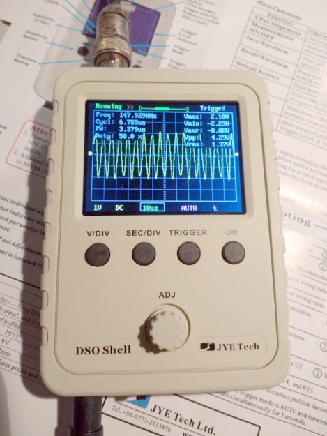
The DSO150 showing the upper end of its bandwidth.
In use, the DSO150 makes a simple and straightforward enough oscilloscope. The usual volts/division and timebase selection is easy enough, and the various trigger modes can quickly be selected. If you’ve used an oscilloscope before then you will have no problems getting started with it. But of course, the DSO150 isn’t just a simple oscilloscope, it’s a digital storage ‘scope. And with 1024 sampling points it can do the usual storage ‘scope thing of allowing the user to examine a stored waveform in great detail, scrolling back and forth through the stored points. Here the instruction sheet falls short, not mentioning that a double tap on the V/div or Sec/div buttons allows you to scroll.
Connecting the signal generator to our DSO150 allowed the exploration of its bandwidth. The claimed 200kHz is pretty spot-on, winding the signal generator far beyond that point showed a tail-off in displayed amplitude. Also the minimum 10µS per division limits the usefulness of a waveform display at these frequencies.
The DSO150 is supplied with a short test lead terminated in a pair of crocodile clips. This is somewhat less useful than the oscilloscope probes we’re used to, though happily it can also be used with a standard 1x/10x probe. Looking at the square wave on the test terminal through a standard probe reveals a sharp corner on the waveform, so there seems not to be any problems between the compensation on-board and that in the probe. It’s likely that either the DSO150 here will be used with a standard probe, or that the crocodile clip will swiftly be replaced with a probe of some kind.
Closing Thoughts
So then, the JYE Tech DSO150 oscilloscope kit. A nice little ‘scope within the limitations of the STM32F103C8 microcontroller that drives it. If you can put up with a 200kHz bandwidth and a 50V peak input voltage then it’s a useful pocket instrument. Its calibration will depend on the STM’s crystal and voltage reference, but as with the rest of its specification, when you consider its pocket-money price those become minor considerations. Add in that its software is open-source, and you have a very nice platform indeed. If we wanted to nitpick we’d ask for a battery compartment and a proper probe, but since both of those would put up the price we wouldn’t make too much noise about it. If you need a pocket ‘scope to supplement your bench scope when working on lower frequencies, or if you have a youngster in the family looking for their first ‘scope, buy one! Our review unit will definitely see some use rather than gathering dust.
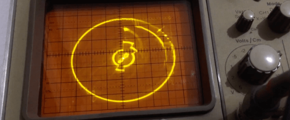
[S-ol] wrote in to share his sweet breakout game played on an oscilloscope. Built in a weekend as part of a game development jam, Plonat Atek is a polar breakout game where the player attacks the center and the ball bounces around the perimeter. You can play it either on an oscilloscope or using an online emulator. [S-ol] wrote the game in Pure Data, a visual programming language for audio. The software controls the audio out channels and uses sound to control the game graphics. He also made use of the Zexy extension for Pure Data.
One of the cool things about this setup is that since the game is programmed with sound, all the sound effects also double as visual effects
We love oscilloscopes, and not just because they’re useful as hell. They also make sweet vector displays, like this analog pong game that uses a scope for a display. Even when they’re not being used for retrogaming they can be capable of some pretty amazing graphics.
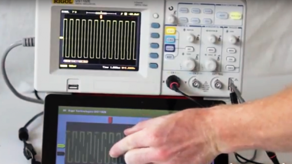
With pervasive smartphones and tablets, the touch interface is assumed for small LCD screens, and we’ve likely all poked and pinched at some screen, only to find it immune to our gestures. Manufacturers have noticed this and begun adding touch interfaces to instruments like digital oscilloscopes, but touch interfaces tend to be an upgrade feature. But thanks to this hybrid oscilloscope touchscreen interface, even the low-end scopes can get in on the action.
It only makes sense that [Matt Heinz] started with one of the most hackable scopes for this build, which was his Master’s thesis project. Using an Android tablet as an auxiliary interface, [Matt] is able to control most of the main functions of the scope remotely. Pinching and expanding gestures are interpreted as horizontal and vertical scaling, while dragging the displayed waveform changes its position and controls triggering. While it’s not a true touchscreen scope, the code is all open source, so can a true aftermarket Rigol touchscreen be far away?
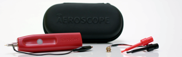
[Martin Rowe] over at EDN recently put a $200 wireless oscilloscope to the test. The Aeroscope 100A is a single channel scope in a probe body that communicates back to an Apple smartphone or tablet via Bluetooth LE. You can see the video from the post, below.
The original prototype of the device had a high bandwidth, but the production model only manages to have a 20 MHz bandwidth at 100 megasamples per second: nothing earth-shattering.

 Where this really stands out is that
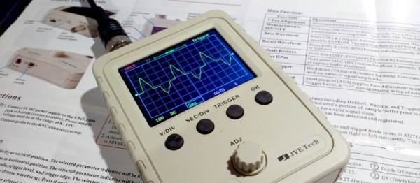

 If you look at most stockists of electronic kits these days, you are likely to find an oscilloscope kit in their range. These are volume produced in China, and the same design trends appear across different models. You can buy surface mount or through-hole, and most of them feature a bare board with maybe a piece of laser-cut Perspex standing in for a case. There are one or two models appearing that come with a case though, and it was one of these that we ordered.