If you are in the market for a temperature controlled soldering iron, an attractive choice of the moment is the TS-100 iron available by mail-order from China. This is an all-in-one iron with a digital temperature controller built into its handle, featuring a tiny OLED display. It’s lightweight, reasonable quality, and all its design and software are available and billed as open source (Though when we reviewed it we couldn’t find an open source licence accompanying the code.) This combination has resulted in it becoming a popular choice, and quite a few software hacks have appeared for it.
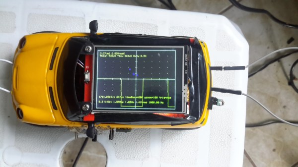
The latest one to come our way is probably best described as coming from the interface between genius and insanity without meaning to disparage the impressive achievement of its author. [Befinitiv] has implemented a working oscilloscope on a TS-100, that uses the soldering iron tip as a probe and the OLED as a display. It requires a small modification to the hardware to bring the iron contact into an ADC pin on the microcontroller, and there is currently no input protection on it so the iron could easily be fried, but it works.
It is strongly suggested in the write-up that this isn’t a production-ready piece of work and that you shouldn’t put it on your iron. At least, not without that input protection and maybe a resistive divider. But for all that it’s still an impressive piece of work, a working soldering iron that becomes a ‘scope on a menu selection. Take a look at the ‘scope-iron in action, we’ve posted a video below the break.
Continue reading “Part Soldering Iron, Part Hand-Held Oscilloscope”