We’ve said it before: building one-offs is different from building at scale. Even on a small scale. There was a time when it was rare for a hobbyist to produce more than one of anything, but these days, access to cheap PC boards makes small production runs much more common. [VoltLog], for example, is selling some modules and found he was spending a lot of time testing the boards. The answer? A testing jig for his PC board.
Big factories, of course, have special machines for bulk testing. These are usually expensive. [VoltLog] found a place specializing in creating custom test jigs using 3D printing.
They also have some standard machines. He did have to modify his PCB to accommodate special test points. He sent the design files to the company, and they produced a semi-custom testing jig for the boards in about a month.
Readers of a certain vintage will no doubt remember that for a brief time, some alkaline batteries came with a built-in battery tester. Basically, you just pushed really hard with your fingernails on the two ends of the strip, and it either lit up the little strip (or didn’t if it was dead), or made the word ‘good’ appear if energized.
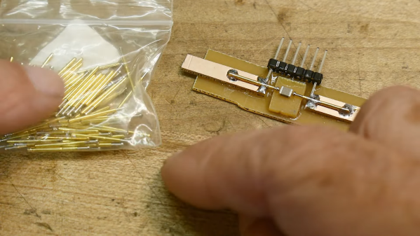
But those days are long gone. What you need now is to either grab the voltmeter, stick out your tongue, or build yourself a battery-testing business card. Even the normies will enjoy this one, mostly because LEDs. Forty-seven of them to be exact, which will come to life and demonstrate that [Greg] is capable of making working electronic gadgets. No way does this card end up at the bottom of a desk drawer.
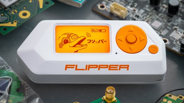
As far as grasping the batteries goes, [Greg] had several ideas, but ultimately landed on pogo pins, which we think is a fabulous solution. Be sure to check out the neat interactive BOM, somewhere in the middle of which is the CH32v003 RISC-V microcontroller. In the video after the break, you can see [Greg] using a Flipper Zero to program it.
There’s no denying how useful surface mount technology is, and how enabling the ability to make really small circuits has become. It comes at a price, though; most of us probably know what it’s like for the slightest wrong move to send a part the size of a grain of sand into another dimension.
To help make testing these parts a little easier, [IMSAI Guy] has come up with this clever little SMD test fixture. It’s designed to hook up to another custom board, which in turn connects to a wonderful old Hewlett-Packard 4275A LCR meter. The jig is based on two pogo pins mounted directly across from each other on a scrap of single-clad PCB. The spring-loaded contacts, which short together when not in use, are pulled apart to load an SMD part, like the 1-μH inductors shown in the video below. The pins hold the component firmly and make good electrical contact, allowing hands-free testing without the risk of an errant touch of the test probes sending it flying.
While the test fixture works well for larger SMDs, we could see this being a bit fussy for smaller parts. That would be easy enough to fix with perhaps some 3D-printed arms that retract the pogo pins symmetrically, holding them open until the part is loaded. A centering fixture might help too, as would a clear shield to contain any parts that get the urge to go for a ride. But, for the tactical application [IMSAI Guy] has in mind, this sure seems like enough.
[Martin] sent this query, along with the lead photo, into the tip line, and he makes a good point. Most development and evaluation boards have multiple rows of pin headers, often arriving loose in the package — soldering is left to the user. In an abundance of caution, we usually design our prototype boards with many pin headers for debugging and testing. But as [Martin] reminds us, there are other alternatives to solder.
Yours truly once worked with a prolific designer of PIC microprocessor boards. Long before the advent of solutions like the Tag Connect family, [Ralph] would program his boards by just inserting a pin header into the PCB and applying gentle pressure with his thumb until the code finished flashing.
You may have seen the staggered offset PCB patterns that hold your pin header securely while you solder. You could tweak this a little bit to put more pressure on the pins, making a solder-less connection that is sufficient for temporary testing.
Taking the opposite approach, you can get solderless connectors with press-fit pins, a method we tested a few years ago on a Raspberry Pi Zero. Anyone who has worked on Eurocard-based systems like VME can appreciate the time-savings and improved reliability of 96-pin DIN-41612 press-fit connectors.
Or, as [Martin] proposes, you could use one of these inexpensive pogo-pin clamps. These are available for less than $10 from your favorite Asian electronics distributor. They are about the size of a large clothespin, and are available in several different pin configurations.
Tag-Connect Style of Connector
Uncle Pete’s Footprint Experiments, Sparkfun
Press-FIt 96-Pin DIN
Pogo-Pin Clamp Fixture
These techniques won’t help you if you need to plug your board into another card, such as a hat onto a Raspberry Pi. But when you just want to grab a few signals for a serial port or probing some digital I/O signals, having a few of these clips in your tool box can save you the time and headache of soldering down a header. Do you have any tips for making soldering pin headers easier, or even avoiding them altogether? Let us know in the comments below.
Flipper Zero is an open-source multitool for hackers, and [Pavel] recently shared details on what goes into the production and testing of these devices. Each unit contains four separate PCBs, and in high-volume production it is inevitable that some boards are faulty in some way. Not all faults are identical — some are not even obvious — but they all must be dealt with before they end up in a finished product.
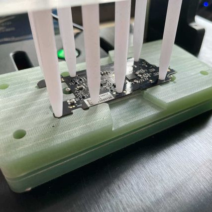
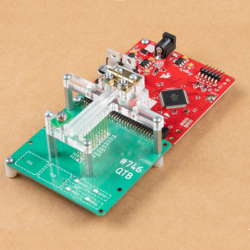
One of several custom test jigs for Flipper Zero. Faults in high volume production are inevitable, and detecting them early is best.
Designing a process to effectively detect and deal with faults is a serious undertaking, one the Flipper Zero team addressed by designing a separate test station for each of the separate PCBs, allowing detection of defects as early as possible. Each board gets fitted into a custom test jig, then is subjected to an automated barrage of tests to ensure everything is as expected before being given the green light. A final test station gives a check to completed assemblies, and every test is logged into a database.
It may seem tempting to skip testing the individual boards and instead just do a single comprehensive test on finished units, but when dealing with production errors, it’s important to detect issues as early in the workflow as possible. The later a problem is detected, the more difficult and expensive it is to address. The worst possible outcome is to put a defective unit into a customer’s hands, where a issue is found only after all of the time and cost of assembly and shipping has already been spent. Another reason to detect issues early is that some faults become more difficult to address the later they are discovered. For example, a dim LED or poor antenna performance is much harder to troubleshoot when detected in a completely assembled unit, because the fault could be anywhere.
Test and programming fixtures are great time-savers for anyone who needs to deal with more than a handful of PCBs. Instead of plugging in connectors (or awkwardly holding probe tips or wires) to program some firmware or run tests, one simply pops a PCB into a custom fixture with one hand, and sips a margarita with the other while a program decides whether everything is as it should be. Test fixtures tend to be custom-made for specific board layouts, meaning one tester is needed per board or device type, but this work is easily justified by the huge time savings they offer.
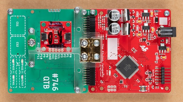
An inserted PCB sits atop the thick acrylic piece, with pogo pins making contact from below. Generous space on the left and right make sure there is clearance for any mounted components. Visible near the bottom of the green board are output LEDs, and two touch-sensitive pads.
The test unit looks like pretty familiar stuff at first glance: some hardware responsible for running the test program, laser-cut acrylic jig to hold a test PCB in a consistent position, spring-loaded pogo pins to make temporary electrical connections, and LEDs to clearly indicate PASS and FAIL states. The clever part is the way the fixture is designed to accommodate multiple board designs, and how it uses several 74LVC4066 quad bilateral switch ICs to take care of switching which pogo pins are connected and to where.
As mentioned, to be compatible with multiple boards there must be common design elements to exploit. In Sparkfun’s case, the through-hole connections on their breakout boards are all in a row with standard 0.1″ spacing. By using the aforementioned pogo pins and 4066 ICs, different pinouts can be accommodated and multiple board types can be used without any need to swap to different test hardware.
Of all the input devices, the keyboard is the greatest. This comes at a cost, though: there were times back in the Before Days, when video and music editing applications came with custom keyboards. There were Pro Tools keyboards, Final Cut keyboards, and innumerable Adobe keyboards. What’s the solution to this problem? More keyboards, obviously, and this time we’ll make them modular.
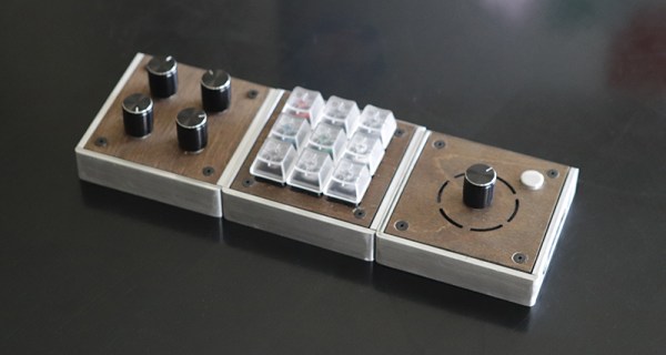
For his Hackaday Prize entry, [Cole B] is building modular, programmable USB keyboards. It’s got everything: a standard 3×3 keypad, a keyboard that’s just four potentiometers, a keyboard that’s a rotary encoder, and a keyboard that’s a set of faders.
The design of these keyboards is inherently modular, and that means there needs to be a way to connect all these modules together, preferably without a bunch of USB cables strewn about. Right now, the best idea [Cole] is working with is pogo pins and magnets. It’s a great idea although Apple Thinks Differently™ and probably wouldn’t be too keen on seeing the whole ‘magnets and pins’ idea stolen out from under them.
Nevertheless, it’s an excellent project that shows how far you can go with manufacturing on a limited budget. These are fantastic keyboard modules already, and the connector scheme already pushes this project into the upper echelon of keyboard hacks.