Playing a video game online is almost second nature now. So much so that almost all multiplayer video games have ditched their split-screen multiplayer modes because they assume you’d rather just be alone at your house than hanging out with your friends. This wasn’t always the case though. In the early days of online multiplayer, systems had to rely on dial-up internet before broadband was readily available (and still had split screen if you didn’t even have that). Almost no one uses dial up anymore though, so if you still like playing your old Dreamcast you’re going to have to do some work to get it online again.
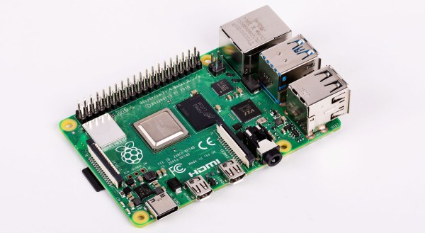
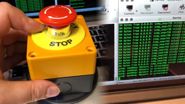
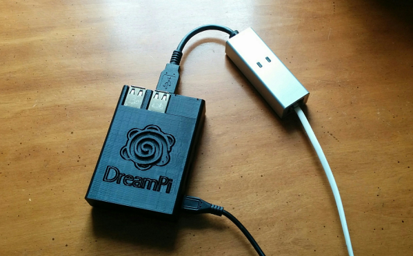
Luckily for all of us there’s a Raspberry Pi image to do almost anything now. This project from [Kazade] uses one to mimic a dial-up connection for a Dreamcast so you can connect with other people still playing Quake 20 years later. It’s essentially a network bridge, but you will need some extra hardware because phone lines use a high voltage line that you’ll have to make (or buy) a solution for. Once all the hardware is set up and working, you’ll need to make a few software configuration changes, but it’s a very straightforward project.
Granted, there have been ways of playing Dreamcast games online before, but this new method really streamlines the process and makes it as simple as possible. The Dreamcast was a great system, and there’s an argument to be made that the only reason it wasn’t more popular was that it was just slightly too far ahead of its time.
Thanks to [Rusty] for the tip!