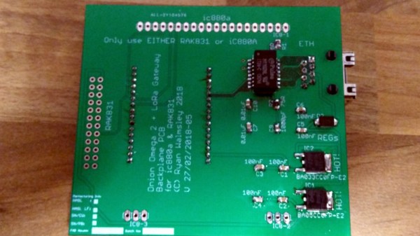
Making A Classic Chip From Discretes

A hackspace discussion of voltage regulators within our earshot touched on the famous μA723, then moved on to its competitors. Kits-of-parts for linear regulators were ten-a-penny in the 1970s, it seems. A rambling tale ensued, involving a Lambda power supply with a blown-up chip, and ended up with a Google search for the unit in question. What it turned up was a hack from 2014 that somehow Hackaday missed at the time, the replication by [Eric Schlaepfer] of an out-of-production regulator chip using surface-mount semiconductors when his Lambda PSU expired.

Lambda were one of those annoying electronics companies with a habit of applying their own part numbers to commonly available chips in an effort to preserve their spares sales. Thus the FBT-031 in this Lambda PSU was in fact a Motorola MC1466, a dirt-cheap common part in the 1970s. Unfortunately though unlike the 723 the MC1466 has long passed out of production, and is rarer than the proverbial hen’s tooth.

Happily, these chips from the early 1970s were often surprisingly simple inside. The MC1466 schematic can be found on its data sheet, and is straightforward enough to replicate with surface-mount discrete components. He thus created a PCB that replicated the original pin layout even though it overlapped the original footprint. A few parts were slightly unusual, dual transistor arrays and a matched triple diode, but the result proved to be a perfect replacement for a real MC1466. Of course a project like this is almost too simple for [Eric], who went on to build the incredible Monster 6502.

If the data sheet lacks a schematic, never fear. You can always try reverse engineering the chip directly.

Circuit Challenge: Two Transistor 3.3V Regulator

[Kevin Darrah] wanted to make a simple 3.3V regulator without using an integrated circuit. He wound up using two common NPN transistors and 4 1K resistors. The circuit isn’t going to beat out a cheap linear regulator IC, but for the low component count, it is actually pretty good.

In all fairness, though, [Kevin] may have two transistors, but he’s only using one of them as a proper transistor. That one is a conventional pass regulator like you might find in any regulator circuit. The other transistor only has two connections. The design reverse biases the base-emitter junction which results in a roughly 8V breakdown voltage. Essentially, this transistor is being used as a poor-quality Zener diode.

Continue reading “Circuit Challenge: Two Transistor 3.3V Regulator”

Not Your Typical ATX Bench PSU

We know what you’re thinking — yet another scrap PC power supply turned into a bench PSU. But look a little closer and you’ll see a nicely designed linear bench supply that just fits inside a gutted ATX case.

A lot of the items on [Medzik]’s BOM for this build are straight from the scrap bin. The aforementioned ATX supply case is one, as is the power transformer donated by a friend. Modules such as the 30V/2A regulator, the digital volt/ammeter, and a thermostat module to control the fan at higher power settings were all sourced via the usual suspects. The PSU boasts two outputs — an adjustable 0-22 volt supply, and a fixed 12-volt output. An unusual design feature is a secondary input which uses the 22-VAC supply from a Weller soldering station to give the PSU a little more oomph. This boosts the maximum output to 30 volts; one wonders why [Medzik] didn’t just source a bigger transformer, but you work with what you have sometimes. There are some nice touches, too, like custom-printed vinyl overlays for the case.

It’s a good-looking and compact unit with a decent suite of features, and you could do a lot worse when building your next bench supply. If it’s not your cup of tea though, just take your pick — tiny and yellow, built to last, or ensconced in Ultrasuede.

A Lesson On Zener Regulators

For the longest time, Zener diode regulators have been one of those circuits that have been widely shared and highly misunderstood. First timers have tried to use it to power up their experiments and wondered why things did not go as planned. [James Lewis] has put up a worth tutorial on the subject titled, “Zener Diode makes for a Lousy Regulator”  that clarifies the misconceptions behind using the device.

[James Lewis] does an experiment with a regulator circuit with an ESP8266 after a short introduction to Zener diodes themselves. For the uninitiated, the Zener diode can operate in the reverse bias safely and can do so at a particular voltage. This allows for the voltage across the device to be a fixed value.

This, however, depends on the current flowing through the circuit which in turn relies on the load. The circuit will work as expected for loads the draw a small amount of current. This makes it suitable for generating reference voltages for microcontrollers and such.

To make a Zener into a “proper” voltage regulator, you just need to buffer the output with an amplifier of some kind. A single transistor is the bare minimum, but actually can work pretty well. You might also add a capacitor in parallel with the Zener to smooth out some of its noise.

Zener diodes are wonderful little devices and write-ups like these are indispensable for beginners and should be shared more often like the Zener and Schottky Tutorial and Diodes as a Switch.


Current Sink Keeps The Smoke In

One of the most versatile tools on anyone’s work bench, at least as far as electrical projects are concerned, is a power supply. Often we build our own, but after we’ve cobbled together some banana jacks with a computer’s PSU or dead-bug soldered a LM317 voltage regulator to a wall wart, how will that power supply perform? Since it’s not desirable to use a power supply that’ll let the smoke out of everything it powers (or itself, for that matter) a constant current sink, or load, can help determine the operating limits of the power supply.

[electrobob] built this particular current sink from parts he had lying around. The theory of a constant current sink is relatively straightforward so it’s easily possible to build one from parts out of the junk drawer, provided you can find a few transistors, fuses, an op amp, and some heat sinks. The full set of schematics that [electrobob] designed can be found on his main project page. He’s also gone a step further with this build as well, since he shorted out his first prototype and destroyed some of the transistors. But, using a few extra transistors in his design also improves the safety and performance of the load, so it’s a win-win.

This constant current load also has the added feature of being able to interface with a waveform generator (an Analog Discovery, specifically) and as a result can connect and disconnect the load quickly. If you aren’t in need of an industrial-grade constant current sink and you have some spare parts lying around, this would be a great one to have around the work bench.

Get To Know Voltage Regulators With A 723

“Chapter 5; Horowitz and Hill”. University students of all subjects will each have their standard texts of which everyone will own a copy. It will be so familiar to them as to be referred to by its author as a shorthand, and depending on the subject and the tome in question it will be either universally loathed or held onto and treasured as a lifetime work of reference.

For electronic engineers the work that most exemplifies this is [Paul Horowitz] and [Winfield Hill]’s The Art Of Electronics. It definitely falls into the latter category of course books, being both a mine of information and presented in an extremely accessible style. It’s now available in its third edition, but the copy in front of me is a first edition printed some time in the mid 1980s.

The Art of Electronics, on regulators.

Chapter 5 probably made most of an impression on the late-teenage me, because it explains voltage regulation and power supplies both linear and switching. Though there is nothing spectacularly challenging about a power supply from the perspective of experience, having them explained as a nineteen-year-old by a book that made sense because it told you all the stuff you needed to know rather than just what a school exam syllabus demanded you should know was a revelation.

On the first page of my Art of Electronics chapter 5, they dive straight in to the μA723 linear voltage regulator. This is pretty old; a design from the legendary [Bob Widlar], master of analogue integrated circuits, which first made it to market in 1967. [Horowitz] and [Hill] say “Although you might not choose it for a new design nowadays, it is worth looking at in some detail, since more recent regulators work on the same principles“. It was 13 years old when they wrote that sentence and now it is nearly 50 years old, yet judging by the fact that Texas Instruments still lists it as an active product without any of those ominous warnings about end-of-life it seems plenty of designers have not heeded those words.

So why is a 50-year-old regulator chip still an active product? There is a huge range of better regulators, probably cheaper and more efficient regulators that make its 14-pin DIP seem very dated indeed. The answer is that it’s an incredibly useful part because it does not present you with a regulator as such, instead it’s a kit of all the parts required to make a regulator of almost any description. Thus it is both an astonishingly versatile device for a designer and the ideal platform for anyone wanting to learn about or experiment with a regulator.
Continue reading “Get To Know Voltage Regulators With A 723”

DIY Pressure Regulator For Exciting SCUBA

To get a SCUBA certification, a prospective diver will need to find a dive shop and take a class. Afterwards, some expensive rental equipment is in order. That is, unless you’re [biketool] who has found a way to build some of his own equipment. If you’re looking for a little bit of excitement on your next dive, this second stage regulator build might be just the thing for you.

It’s worth noting that [biketool] makes it explicitly clear that this shouldn’t be used on any living being just yet. The current test, though, was at 120 PSI using some soda bottles and some scrap bike parts. The OpenSCAD-designed regulator seems to work decently well for something that’s been homemade using some 3D-printed parts and other things available to most tinkerers/makers/hackers. [biketool] also goes over some issues with the regulator leaking and discusses porosity issues inherent in FDM printing but overall this project looks promising. Whether or not you want a pressurized 3D printed vessel that close to your face is rife for debate.

We don’t see a lot of SCUBA-related hacks around here. After all, it’s one thing to power an air horn with SCUBA tanks, but it’s a completely different thing to build something that keeps you from drowning.

Thanks to [dave] for the tip!