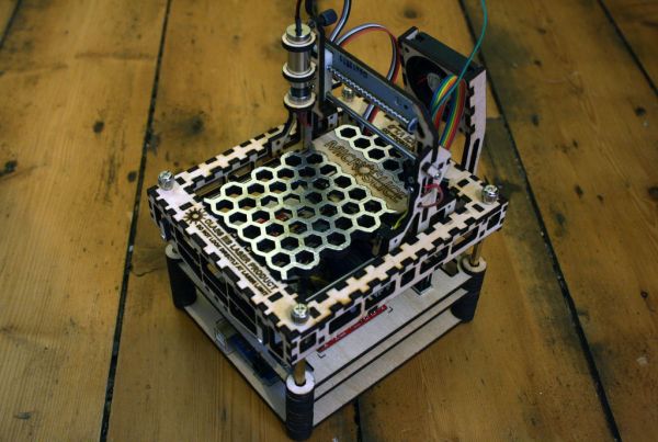
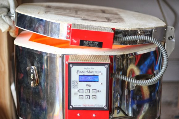
 [Richard]’s wife scored an Evenheat glass-fusing kiln, but the 20-year-old temperature controller was broken. He could have simply ordered a replacement controller, but that kind of problem solving doesn’t get you on Hack a Day. His wife wanted more control over the kiln and he convinced her that building their own was the way to go. Thus, the Meltinator 9000 was born.
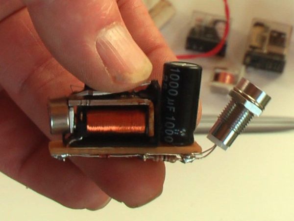
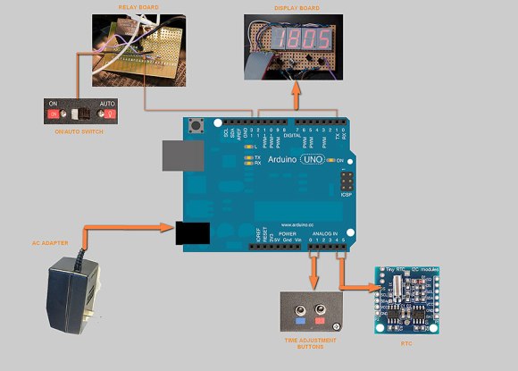
[Richard]’s design uses an Arduino Uno and an Adafruit display shield, protoshield, and thermocouple reader board. He built a simple relay driver with a resistor, BJT, and a diode and connected it to pin 13 and its built-in indicator. To [Richard]’s delight, all of this fit in the original enclosure.
[Richard]’s software provides 25 fusing schedules with ten steps apiece. Each step has a target temperature, rate of temperature change, and a hold time which can be increased on the fly. He ran a test program that heated the kiln to 1500°F at a rate of 2550°F/hour. He then cooled it to 500°F at a rate of 1000°F/hour, which took longer than he thought. The good news is that the kiln is well-insulated! [Richard] has the software available on his GitHub.
Don’t have a glass kiln? Prefer to control beer-related temperatures? You could always hack your stove in the name of homebrewing.
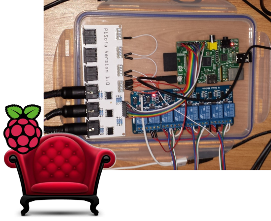
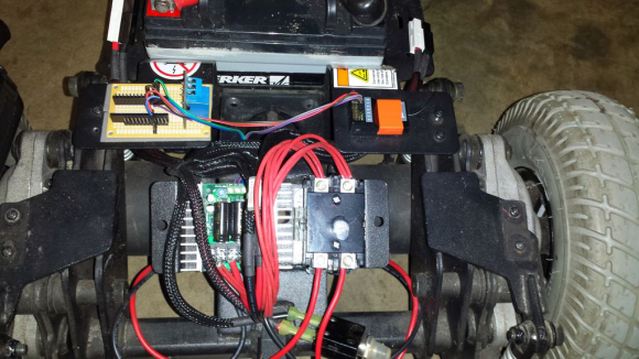 Okay, so he doesn’t have Grandma riding in it that we know of, but [zim] recently decided to turn a Jazzy mobility chair into “a radio-controlled platform for mischief”. RC offers more range than wifi or bluetooth, and he was able to find a reasonably priced secondhand radio on Craigslist. However, he found out that in the event of signal loss, the receiver keeps sending the last commands to the speed controller. [zim] didn’t want his 150 lb (68kg) mischief platform getting loose, so