Sometimes I get enough away from writing about other people’s accomplishments long enough to actually do my own hacks. Most recently I developed a combination lock that opens the garage door. The idea isn’t original, it is based on [Alan Parekh’s] button code project, but I did develop my own hardware and software. A four digit code is entered by pressing the button a number of times for the first digit, and waiting for a flash of an LED inside before moving on to the next digit. If the correct code is entered the door opens.
My version centers around an ATtiny13. I originally downloaded [Alan’s] code in hopes that I could port the PIC firmware over pretty easily. Unfortunately it was written in BASIC so I just took what I knew about the interface and wrote my own program. I developed on an ATmega168 so that I would have no trouble running out of programming space, and was able to optimize my code down to 964 bytes to fit on the tiny13.
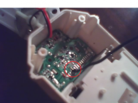
The hardware is quite simple. I purchased a lighted doorbell from Home Depot and swapped out the light bulb for an LED. I choose this because the doorbell mounts in a 5/8″ hole in the trim of the garage door and is easily overlooked. I’m quite happy with the results, and if you want to play around with the idea, you can easily build the circuit on a breadboard and use another LED for the load rather than including a relay. Hit the link at the top of this post for the schematic, code, and build images.