This series of monthly teardowns was started in early 2018 as an experiment, and since you fine folks keep reading them, I keep making them. But in truth, finding a new and interesting gadget every month can sometimes be a chore. Which is why I’m always so thankful when a reader actually sends something in that they’d like to see taken apart, as it absolves me from having to make the decision myself. Of course it also means I can’t be blamed if you don’t like it, so keep that in mind as well.
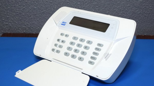
Coming our way from the tropical paradise of Eastern Pennsylvania, this month’s subject is an ADT branded Impassa SCW9057G-433 alarm system that was apparently pulled off the wall when our kind patron was moving house. As you might have guessed from the model number, this unit uses 433 MHz to communicate with various sensors and devices throughout the home, and also includes a 3G cellular connection that allows it to contact the alarm monitoring service even if the phone line has been cut.
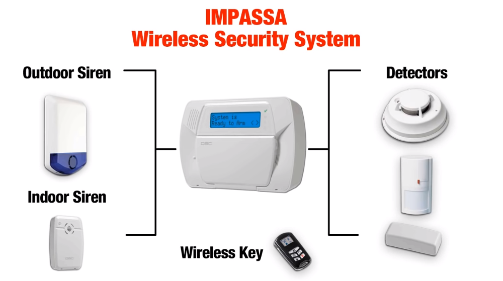
From how many of these are on eBay, and the research I’ve done on some home alarm system forums, it appears that you can actually pick one of these up on the second-hand market and spin your own whole-house alarm system without going through a monitoring company like ADT. The extensive documentation from Impassa covers how to wire and configure the device, and as long as the system isn’t locked when you get it, it seems like wiping the configuration and starting from scratch isn’t a problem.
If it’s possible to put together your own homebrew alarm system with one of these units at the core, then it seems the least we can do is take it apart and see what kind of potentially modifiable goodies are waiting under that shiny plastic exterior.
Continue reading “Teardown: Impassa SCW9057G-433 Alarm System”