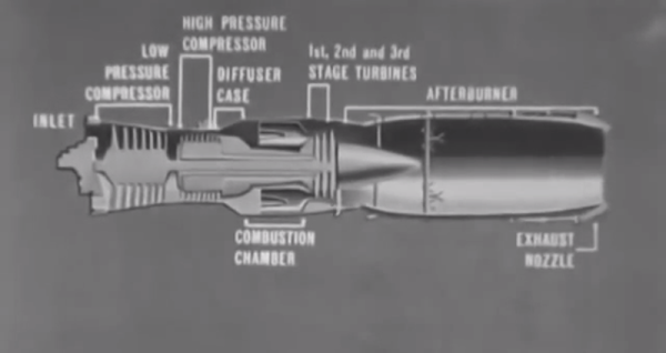
The J-57 afterburner engine appeared in many airplanes of notable make, including the F-101, -102, and -103. This USAF training film shows the parts of the J-57, explains the complex process by which the engine produces thrust, and describes some maintenance and troubleshooting procedures.
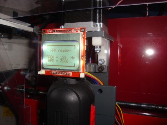
The name of this game is high performance. Precision thrust requires careful rigging of the engine’s fuel control linkage through a process called trimming. Here, the engine fuel control is adjusted with regard to several different RPM readings as prescribed in the manual.
One of the worst things that can happen to a J-57 is known as overtemping. This refers to high EGT, or exhaust gas temperature. If EGT is too high, the air-fuel ratio is not ideal. Troubleshooting a case of high EGT should begin with a check of the lines and the anti-icing valve. If the lines are good and the valve is closed, the instruments should be checked for accuracy. If they’re okay, then it’s time for a pre-trimming inspection.
In addition to EGT, engine performance is judged by RPM and PP7, the turbine discharge pressure. If RPM and PP7 are within spec and the EGT is still high, the engine must be pulled. It should be inspected for leaks and hot spots, and the seals should be examined thoroughly for cracks and burns. The cause for high EGT may be just one thing, or it could be several small problems. This film encourages the user to RTFM, which we think is great advice in general.
Continue reading “Retrotechtacular: The J-57 Afterburner Engine”
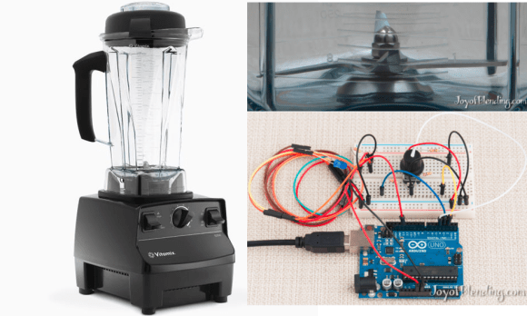 Some people really love their smoothies. We mean really, really, love smoothies and everything about making them, especially the blenders. [Adam] is a big fan of blenders, and wanted to verify that his Vitamix blenders ran as fast as the manufacturer claimed. So he built not one, but