Converting Bluetooth Sensors To Zigbee

With the increase in popularity of Internet of Things (IoT) devices and their need to communicate wirelessly,  there’s been a corresponding explosion of wireless protocols to chose from. Of course there’s Wi-Fi and Bluetooth, but for more specialized applications there are some other options like Z-Wave, LoRa, Sigfox, and Thread. There’s a decent amount of overlap in their capabilities too, so when [SHS] was investigating some low-cost Xiaomi sensors it was discovered that it is possible to convert them from their general purpose Bluetooth protocol over to the more IoT-specialized Zigbee protocol instead.

These combination temperature and humidity sensors have already been explored by [Aaron Christophel] who found that it’s possible to flash these devices with custom firmware. With that background, converting them from Bluetooth to Zigbee is not a huge leap. All that’s needed is the Zigbee firmware from [Ivan Belokobylskiy] aka [devbis] and to follow the steps put together by [SHS] which include a process for flashing the firmware using an over-the-air update and another using UART if the wireless updates go awry. Then it’s just a short process to pair the new Zigbee device to the network and the sensor is back up and running.

Converting from one wireless protocol to another might not seem that necessary, but using Bluetooth as an IoT network often requires proxy nodes as support devices, whereas Zigbee can communicate directly from the sensor to a hub like Home Assistant. Other Zigbee devices themselves can also act as a mesh network of sorts without needing proxy nodes. The only downside of this upgrade is that once the Bluetooth firmware has been replaced, the devices no longer has any Bluetooth functionality.

Thanks to [RoganDawes] for the tip!

Capacitive Rainmeter Measures The Sky Water Just Fine

If you’ve got a smart home, or you just want to know how soaked your garden is getting in the winter, you might want to measure rainfall. There are a bunch of ways to go about it, and this capacitive rainmeter solution from [Magnus Thome] might just be the perfect solution you’re looking for.

Like many who came before, [Magnus] had experimented with traditional resistive-based sensors using copper traces to measure water levels. As the soil moisture measuring set learned as well, corrosion tends to promise a pretty short life for these designs. Capacitive sensors, on the other hand, can be isolated from the water itself, and thus sense the levels without being subject to such degradation.

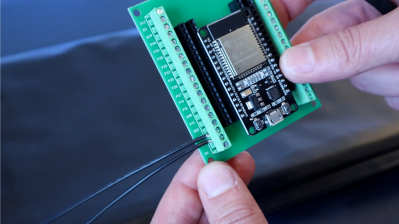
[Magnus] pairs the off-the-shelf capacitive sensor with an ESP32 charged with reading it and reporting back to Home Assistant. It’s also outfitted with a heater to keep it at a constant temperature to avoid it freezing over during those cold and snowy Swedish winters.

It’s a tidy way to integrate a quality commercial sensor with a DIY smart home setup. If you’ve been whipping up your own neat sensor networks for your smart home, don’t hesitate to let us know. Video after the break.

Continue reading “Capacitive Rainmeter Measures The Sky Water Just Fine”

Simple CMOS Circuit Allows Power And Data Over Twisted-Pair Wiring

If you need to send data from sensors, there are plenty of options, including a bewildering selection of wireless methods. Trouble is, most of those protocols require a substantial stack of technology to make them work, and things aren’t much easier with wired sensors either. It doesn’t have to be that complicated, though, as this simple two-wire power-and-data interface demonstrates.

As with all things electronic, there are tradeoffs, which [0033mer] addresses in some detail in the video below. The basic setup for his use case is a PIC-based sensor — temperature, for this demo — that would be mounted in some remote location. The microcontroller needs to be powered, of course, and also needs to send a signal back to a central point to indicate whether the monitored location is within temperature specs. Both needs are accommodated by a single pair of wires and a tiny bit of additional circuitry. On one end of the twisted pair is a power supply and decoder circuit, which sends 9 volts up the line to power the PIC sensor. The decoder is based on a CD4538 dual monostable multivibrator, set up for an “on” time of one second. A trigger input is connected to the power side of the twisted pair going to the sensor, where a transistor connected to one of the PIC’s GPIO pins is set up to short the twisted pair together every half-second. Power to the PIC is maintained by a big electrolytic and a diode, to prevent back-feeding the controller. The steady 0.5-Hz stream of pulses from the sensor keeps resetting the timer on the control side. Once that stream stops, either through code or by an open or short condition on the twisted pair, the controller triggers an output to go high.

It’s a pretty clever system with very simple and flexible circuitry. [0033mer] says he’s used this over twisted-pair wires a couple of hundred feet long, which is pretty impressive. It’s limited to one bit of bandwidth, of course, but that might just be enough for the job. If it’s not, you might want to check out our primer on current-loop sensors, which are better suited for analog sensors but still share some of the fault-detection features.

Continue reading “Simple CMOS Circuit Allows Power And Data Over Twisted-Pair Wiring”

3D Printing Improves Passive Pixel Water Gauge

Here at Hackaday, we feature all kinds of projects, and we love them all the same. But some projects are a little easier to love than others, especially those that get the job done in as simple a way as possible, with nothing extra to get in the way. This completely electronics-free water gauge is a great example of doing exactly as much as needs to get done, and not a bit more.

If this project looks a bit familiar, it’s because we featured [Johan]’s previous version of “Pixel Pole” a few years back. Then as now, the goal of the build is to provide a highly visible level gauge for a large water tank that’s part of an irrigation system. The basic idea was to provide a way of switching a pump on when the tank needed filling, and off when full. [Johan] accomplished this with a magnetic float inside the tank and reed switches at the proper levels outside the tank, and then placed a series of magnetic flip dots along the path of the float to provide a visual gauge of the water level. The whole thing was pretty clever and worked well enough.

But the old metal flip dots were getting corroded, so improvements were in order. The new flip dots are 3D printed, high-visibility green on one side and black on the other. The only metal parts are the neodymium magnet pressed into a slot in the disc and a sewing pin for the axle. The housing for each flip dot is also printed, with each module snapping to the next so you can create displays of arbitrary height. The video below shows printing, assembly, and the display in action.

[Johan]’s improvements are pretty significant, especially in assembly; spot-welding was a pretty cool method to use in the first version, but printing and snapping parts together scales a lot better. And this version seems like it’ll be much happier out in the elements too. Continue reading “3D Printing Improves Passive Pixel Water Gauge”

DIY Repair Brings An X-Ray Microscope Back Into Focus

Aside from idle curiosity, very few of us need to see inside chips and components to diagnose a circuit. But reverse engineering is another story; being able to see what lies beneath the inscrutable epoxy blobs that protect the silicon within is a vital capability, one that might justify the expense involved in procuring an X-ray imager.  But what’s to be done when such an exotic and expensive — not to mention potentially deadly — machine breaks down? Obviously, you fix it yourself!

To be fair, [Shahriar]’s Faxitron MX-20 digital X-ray microscope was only a little wonky. It still generally worked, but just took a while to snap into the kind of sharp focus that he needs to really delve into the guts of a chip. This one problem was more than enough to justify tearing into the machine, but not without first reviewing the essentials of X-ray production — a subject that we’ve given a detailed look, too — to better understand the potential hazards of a DIY repair.

With that out of the way and with the machine completely powered down, [Shahriar] got down to the repair. The engineering of the instrument is pretty impressive, as it should be for something dealing with high voltage, heavy thermal loads, and ionizing radiation. The power supply board was an obvious place to start, since electrostatically focusing an X-ray beam depends on controlling the high voltage on the cathode cup. After confirming the high-voltage module was still working, [Shahriar] homed in on a potential culprit — a DIP reed relay.

Replacing that did the trick, enough so that he was able to image the bad component with the X-ray imager. The images are amazing; you can clearly see the dual magnetic reed switches, and the focus is so sharp you can make out the wire of the coil. There are a couple of other X-ray treats, so make sure you check them out in the video below.

Continue reading “DIY Repair Brings An X-Ray Microscope Back Into Focus”

Hackaday Links Column Banner

Hackaday Links: September 10, 2023

Most of us probably have a vision of how “The Robots” will eventually rise up and deal humanity out of the game. We’ve all seen that movie, of course, and know exactly what will happen when SkyNet becomes self-aware. But for those of you thinking we’ll get off relatively easy with a quick nuclear armageddon, we’re sorry to bear the news that AI seems to have other plans for us, at least if this report of dodgy AI-generated mushroom foraging manuals is any indication. It seems that Amazon is filled with publications these days that do a pretty good job of looking like they’re written by human subject matter experts, but are actually written by ChatGPT or similar tools. That may not be such a big deal when the subject matter concerns stamp collecting or needlepoint, but when it concerns differentiating edible fungi from toxic ones, that’s a different matter. The classic example is the Death Cap mushroom (Amanita phalloides) which varies quite a bit in identifying characteristics like color and size, enough so that it’s often tough for expert mycologists to tell it apart from its edible cousins. Trouble is, when half a Death Cap contains enough toxin to kill an adult human, the margin for error is much narrower than what AI is likely to include in a foraging manual. So maybe that’s AI’s grand plan for humanity — just give us all really bad advice and let Darwin take care of the rest.

Continue reading “Hackaday Links: September 10, 2023”

Clock Runs Computer In Slow-Motion

At the heart of all computers is a clock, a dedicated timepiece ensuring that all of the parts of the computer are synchronized and can work together to execute the instructions that the computer receives. Clock speeds for most modern off-the-shelf computers and smartphones operate around a billion cycles per second, and even clocks that tick at a human-dizzying speed of a million times per second have been around since at least the 1970s. But there’s no reason a computer can’t run at a much slower speed, as [Greg] demonstrates in this video where he slows down a 6502 processor to a single clock cycle per second.

To reduce the clock speed from the megahertz range down to a single hertz or single clock cycle per second, [Greg] is using the pendulum from an actual clock. He attaches a small magnet to the bottom of the pendulum which is counted by a sensor as it swings past. Feeding that pulse into a monostable conditioner yields a clock signal which is usable for one of his 6502-based computers, and at this extremely slow rate, it’s possible to see the operation of a lot of the computers’ inner workings a step at a time. In fact, he optimized the computer’s operation as this slow speed let him see some inefficiencies in the program he was running.

It helps if your processor is static, of course. Older CPUs with dynamic storage for registers and some with limited-range PLLs would not work with this technique. The 8080A, for example, required a clock of at least 500 kHz.

Not only can this computer use a pendulum clock as the basis for its internal clock, but [Greg] also rigged up a mechanism to use a heartbeat. Getting in a little bit of exercise to increase his heart rate first will noticeably increase the computer’s speed. And, if you’re looking to get a deeper glimpse into the inner workings of a computer, we’d recommend looking at one which forgoes transistors in favor of relays.

Continue reading “Clock Runs Computer In Slow-Motion”