We’ve all been there – hiking in the woods with a dead phone battery. No GPS, no way to Tweet that selfie from some hill with a great vista. It’s a disaster! But not if you have access to a little trailside junk and have the ingenuity to build this field-expedient water wheel generator to recharge your phone.
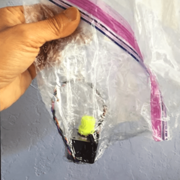
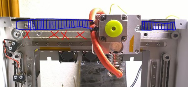
OK, it’s a stretch to imagine finding all the things needed for [Thomas Kim]’s hack. We’re only guessing at the BOM – the video below has little commentary, so what you see is what you get – but it looks like a garbage can at the trailhead might at least yield the materials needed to build the turbine. Water bottle bottoms and a couple of plastic picnic plates form the Pelton-like impeller, the frame looks like an old drying rack, and the axle appears to be a campfire skewer. But you might have a hard time finding the electrical side of the build, which consists of a stepper motor, a rectifier, and an electrolytic cap. Then again, you could get lucky and find a cast-off printer by the side of the road. No matter how he got the materials, it’s pretty cool to see an iPhone recharging next to a babbling brook in the woods.
Looking for a little more oomph from your trash-heap hydroelectric turbine? Maybe you need to look at this washing machine power plant build.
Continue reading “Trash-heap Water Wheel Recharges IPhone In The Woods”


![The 3D scan of a small cave near Louisville (source: [caver.adam's] Sketchfab repository)](https://hackaday.com/wp-content/uploads/2016/06/bildschirmfoto-2016-06-27-um-20-02-11.png)