Your Mug On An Etch A Sketch — Automatically

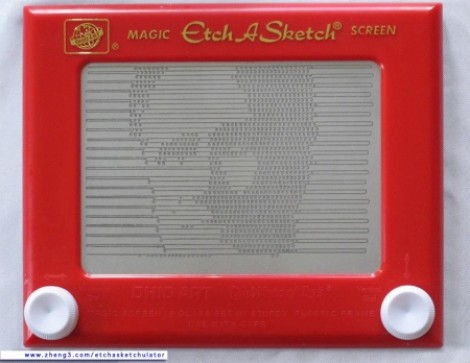
[Jim’s] pretty serious about his Etch a Sketch. He’s gone to the trouble of building a rig that will automatically render a photograph as Etch a Sketch art. Do you recognize the US political figure being plotted in this image? He actually cracks these open and removes all of the internals to preserve the artwork when the reassembled body is ready to be hung on a wall. But we like it for the hacker-friendly interface techniques he used.

He moves the knobs using a pair of stepper motors. They attach thanks to a pair of 3D printed gears he modeled which go over the stock knobs and secure with four set screws. He says he can be up and printing in five minutes using these along with the MDF jig that holds the body and the motors.

He converts photos to 1-bit images, then runs them through ImageMagick to convert them into a text file. A Python script parses that text, sending appropriate commands to an Arduino which drives the motors. The image is drawn much like a scanning CRT monitor. The stylus tracks one horizontal line at a time, drawing a squiggle if the pixel should be black, or skipping it if it should be white.

We wish there was a video of the printing process. Since we didn’t find one, there’s a bonus project unrelated to this one after the break. It’s an Etch a Sketch clock.

Continue reading “Your Mug On An Etch A Sketch — Automatically”

Robotic Whiteboard Writes Your Wall On The Wall

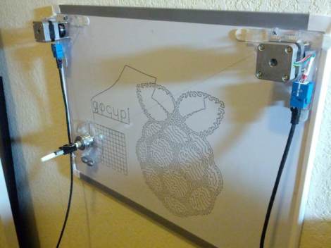
[Dave’s] drawbot writes his Facebook wall messages on a whiteboard. The setup is pretty simple, depending on a pair of stepper motors and common household goods. As you can see in the image, the stylus is a plain old dry-erase marker held by a big spring clip (the kind that holds a stack of papers together). What you can’t see is that there’s a kick stand to hold the writing head away from the board when moving to the next plot point.

In this example a cursive font is being used, but [Dave] included two other fonts in the code. Those require the felt tip to be frequently lifted from the board, and a servo motor does this by pressing a cotton swab against the surface. This does erase any marker lines it slides past, but it’s a pretty small area that is lost. To control the motors [Dave] is using the EiBotBoard which was originally designed for the EggBot. It’s got a USB mini-b connector which lets a computer push messages scraped from the Internet. Don’t miss the video demonstration embedded after the break.

A small modification would make this into a pretty nifty light painting rig.

Continue reading “Robotic Whiteboard Writes Your Wall On The Wall”

Automated Turntable Photography

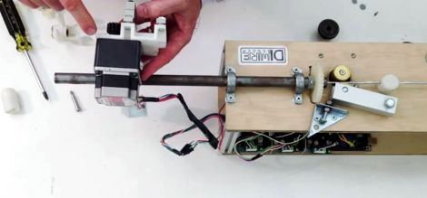
[Muris] has a friend who is selling items on the internet. This friend wanted a simple way to make rotating images of the products and asked him to help. The result of his labors is this base unit that drives the turn table and controls the camera.

The first iteration of the turntable was powered by the stepper motor from a floppy drive. A disc was mounted directly on the motor spindle, but the results were a bit poor. This is because the motor had a fairly low resolution of 200 steps per rotation. That doesn’t allow for smooth animation, and there was a lot of vibration in the system. An upgrade to the geared system you see above included swapping out that motor for one from an old scanner. Now it achieves 1200 steps per rotation and the vibration is gone.

The connectors seen in the base are USB, incoming power, and shutter control. [Muris] wrote a program to control the PIC 16F628A inside the base. The program sends commands via USB and has parameters for number of frames per rotation, direction of rotation, and the like. Set it up as desired, place the product on the turntable, and hit start. Unfortunately there’s no video of this in action because [Muris] gave it to his friend as soon as it was finished. We guess the fact that he didn’t get it back means it’s working great.

If you don’t mind some rough edges and exposed wiring you can throw a system of your own together pretty quickly.

Wind-powered POV Weather Station

The more we think about this one the more we like it. [Michael] built himself a wind-powered persistence-of-vision weather station. Okay, that sounds interesting, but he ups the ante when you find out what’s included in the system.

A stepper motor acts as the generator which powers the electronics. As we’ve seen before; if you spin the shaft of a stepper motor electricity is produced. [Michael] is actually spinning the housing of the motor, with the shaft mounted to the base that holds the weather station in place. This way, the electrical contacts are spinning along with the blades of the generator. By mounting all of the electronics on these blades he gets around the problem of transferring power onto a spinning platform.

A set of LEDs on the end of the blades display temperature and relative humidity readings. A hall effect sensor pulled form an old floppy drive syncs the display with the rotational speed. He’s even got a shunt system which keeps the input voltage at a safe level, and will act as a break in high winds to keep the rotors from spinning out of control. See what we mean? An interesting idea because a fantastic project when you build in features like these!

Investigating The Generative Properties Of A Stepper Motor

You probably know that if you spin a motor (mechanically) it generates electricity on what would normally be the inputs. This can be a problem when you shut off a spinning motor and is the reason that protection diodes are built into motor driver circuits. But [Dino] isn’t interested in driving a motor, he wanted to see what he could do with the electricity generated by spinning a stepper motor.

He built the test rig that you see above for this purpose. In the foreground a 12V DC motor is held in place with an electrical conduit clamp. This connects to the stepper motor being tested using a segment of rubber tube. The DC motor provides a reliable input for his experiments, but could be replaced in the future by a propeller to make it wind powered, or by a water wheel. Check out the video after the break to see what kind of juice [Dino] gets out of it, and how it can be used for powering LEDs, recharging batteries, or driving a motor.

Continue reading “Investigating The Generative Properties Of A Stepper Motor”

High Speed Stepper Driving: 25k Steps Per Second

Stepper motors are pretty easy to control with a microcontroller. But if you’re looking to run then at a high number of revolutions per second things get tricky pretty quickly. [Uwe’s] been learning about and building stepper drivers for years, and recently he decided to build a high-performance driver based on a MicroChip reference design.

As with the reference design, his board uses a dsPIC33. But instead of using a series of discrete MOSFETS to switch the signals to the motor, he sourced an L298N motor driver. That’s it sticking up next to the large capacitor. When driven hard it needs its own heat sink, which [Uwe] cut from a larger CPU heat sink. During development, he decided to use interrupt-based PWM rather than the hardware PWM offered by the dsPIC. It works, but he would go the other route if doing it again.

For the pedestrian, the video after the break has all the details you need. For those that really want to dive in, [Uwe’s] multi-paged write-up is worth bookmarking.

Continue reading “High Speed Stepper Driving: 25k Steps Per Second”

Arduino Boards Control Cheap Clockworks Via Coil Injection

Here’s a couple of clocks that use Arduino boards to control inexpensive clockworks. The concept is quite simple, and perhaps best outlined by [Matt Mets’] article on the subject. As it turns out, these clockworks are driven by a coil, forming a device that is quite similar to a stepper motor. If you solder a wire onto each end of the electromagnetic coil and hook those to a microcontroller, you can alter the speed at which the clock ticks. Just drive one pin high and the other low, then reverse the polarity for the next tick.

The clock you see on the right (translated) is a store-bought cheapy. The Arduino barely visible at the bottom of the image is sending pulses once every second. But as you can see in the video after the break, holding down a button will fast-forward through time. [Sodanam] posted his code as well as pictures of the hardware hack itself.

To the left is a horse of a different color. It’s a clock modeled after the Weasley household clock from the Harry Potter books. The clockwork trick is the same, but the Arduino uses GPS data and NOAA weather information to set the status.

Continue reading “Arduino Boards Control Cheap Clockworks Via Coil Injection”