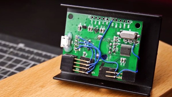
Software Defined Radio (SDR) is a great technology, but there’s something so satisfying about spinning a physical knob to cruise the airwaves. Wanting to restore that tactile experience, [Tysonpower] purchased a cheap USB volume knob and set out to get it working with his software. Unfortunately, getting it up and running took a lot more work than you’re probably expecting.
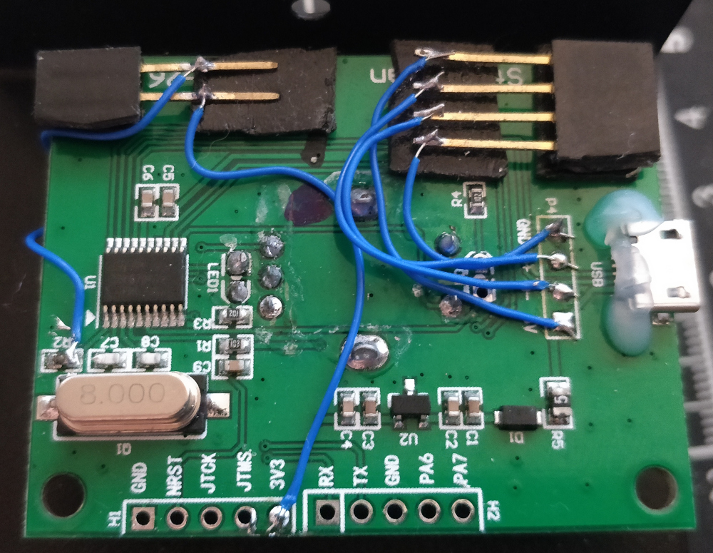
After verifying that the knob worked for volume control on his computer, [Tysonpower] decided to try and pull the firmware from the device’s STM32 microcontroller. Unfortunately, this is where things got tricky. It turned out the chip had Code Protection enabled, so when it was wired up to a programmer and put into DFU mode, the firmware got wiped. Oops.
That left [Tysonpower] with no choice but to write a new firmware from scratch, which naturally required reverse engineering the device’s hardware. Step one was reading up on STM32 development and getting the toolchain working, which paved the way to getting the knob’s LED to blink. A couple more hours worth of work and some multimeter poking later, and he was able to read the knob’s movement. He describes getting USB HID working as a nightmare due to lack of documentation, but eventually he got that sorted out as well.
The end result is a firmware allows the volume knob to mimic a mouse scroll wheel, which can be used for tuning in many SDR packages. But we think the real success story is the experience [Tysonpower] gained with reverse engineering and working with the STM32 platform. After all, sometimes the journey is just as important as the end result. Continue reading “Software Defined Radio Gets Physical Control”