2015 was two years ago, and to the surprise of many, we actually had hoverboards at the time. Of course, these weren’t Back to the Future-style hovering skateboards; they were crappy two-wheeled balancing scooters that suffered a few battery explosions and were eventually banned from domestic flights by some carriers. But oh boy, there were some funny Vines of these things.
While the rest of the world moved on from hoverboards, [Casainho] has been working on Open Sourcing the firmware for these interesting bits of electronics and motors. Now, his work is wrapping up and he has new firmware for electric unicycles and hoverboards.
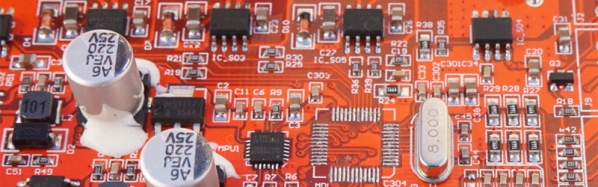
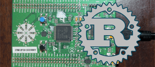
The popular and cheap electric unicycles and hoverboards that have been swimming across the Pacific from the great land of Ali Baba for the past five years are based around a single, cheap controller board. This controller board is built around the STM32F1038T6 microcontroller, and are able to control a pair of three-phase brushless motors. The teardown began on the electric unicycle forum and was completely documented in a GitHub repo.
The Open Source firmware is now mostly complete, although the necessary self-balancing function doesn’t work. We’re thinking that’s alright; with this new firmware, these electric unicycles have a crazy amount of torque and could be the basis for a few very cool builds. You can check out a video of this torque below.
If two wheels seems far too safe, exercise your inner daredevil with a 3D printed unicycle conversion for a hoverboard.
Continue reading “Open Source Firmware For Hoverboards” →