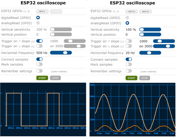
An oscilloscope can be an expensive piece of equipment, but not every measurement needs four channels and gigahertz sampling rates. For plenty of home labs, old oscilloscopes with CRTs can be found on the used marketplace for a song that are still more than capable of getting the job done, but even these can be overpowered (not to mention extremely bulky). If you’re looking for something even cheaper, and quite a bit smaller, this ESP32 scope from [BojanJurca] might fit the bill.
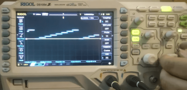
The resulting device manages to keep costs extremely low, but not without a trade-off. For this piece of test equipment, sampling is done over the I2C bus on the ESP32, which can manage a little over 700 samples per second with support for two channels. With the ESP32 connected to a wireless network, the data it captures can be viewed from a browser in lieu of an attached screen, which also keeps the size of the device exceptionally small. While it’s not a speed demon, that’s more than fast enough to capture waveforms from plenty of devices or our own circuit prototypes in a form factor that can fit even the smallest spaces.
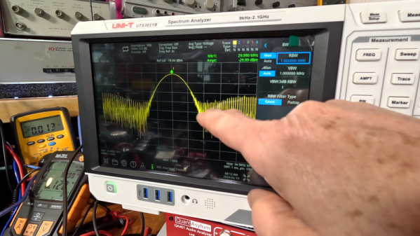
Of course for work on devices with faster switching times, it’s always good to keep a benchtop oscilloscope around. But as far as we can tell this one is the least expensive, smallest, and most capable we’ve come across that would work for plenty of troubleshooting or testing scenarios in a pinch. We’ve seen others based on slightly more powerful microcontrollers like this one based on the STM32 and this other built around the Wio Terminal with a SAMD51, both of which also include built-in screens.
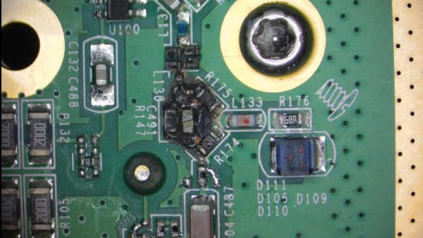
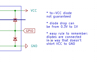 Thankfully, in modern-day Western climates and with modern tech, you are not likely to encounter ESD-caused problems, but they were way more prominent back in the day. For instance, older hackers will have stories of how FETs were more sensitive, and touching the gate pin mindlessly could kill the FET you’re working with. Now, we’ve fixed this problem, in large part because we have added ESD-protective diodes inside the active components most affected.