Many dream of tooling around in a high performance sports car, but the cost of owning, maintaining, and insuring one of them make it a difficult proposition. While this LEGO version of the Corvette ZR1 might not be exactly like the real thing, it’s 4-speed manual and electronic gauge cluster can give you a taste of the supercar lifestyle without having to taken out a second mortgage.

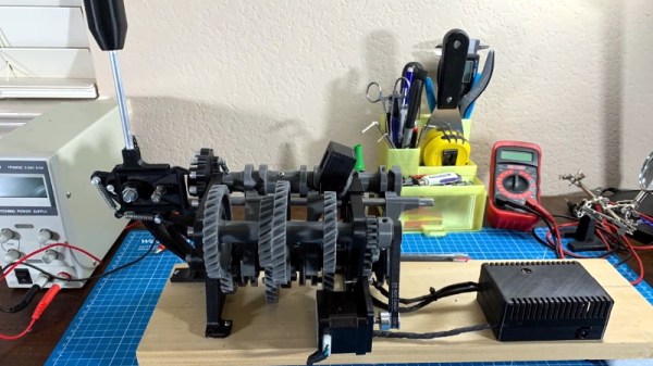
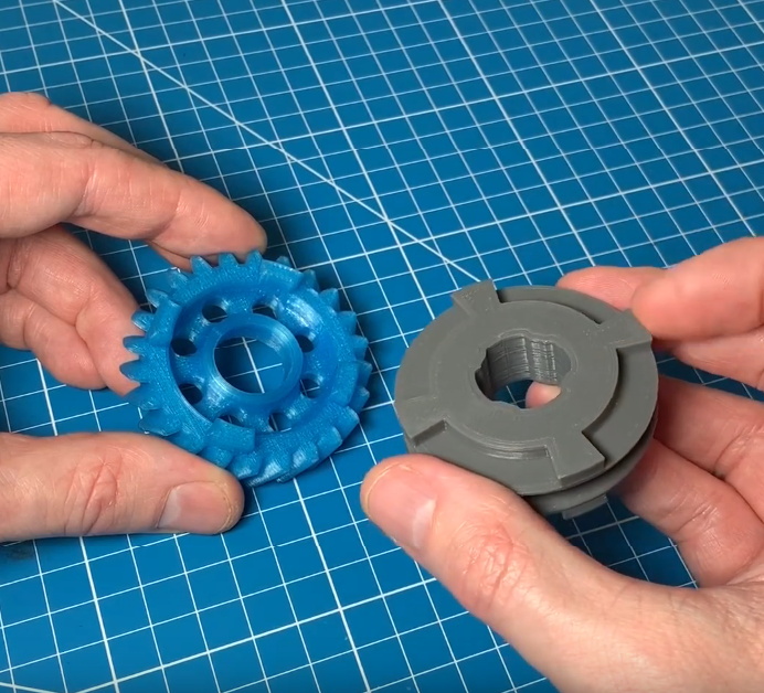
Built by [HyperBlue], this desktop speedster has more going on under the hood (or more accurately, the roof) than you might expect. While it looks pretty unassuming from the outside, once the top is lifted, you can see all the additional components that have been packed in to motorize it. The functional gearbox takes up almost the entire interior of the car, but it’s not like you were going to be able to fit in there anyway.
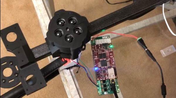
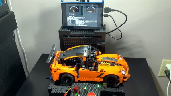
But the motorized car is really only half of the project. [HyperBlue] has built a chassis dynamometer for his plastic ride that not only allows you to “start” the engine with realistic sights and sounds (recorded from an actual GM LT1 V8 engine), but put the mini ‘Vette through its paces. With a virtual dashboard powered by the Raspberry Pi, you can see various stats about the vehicle such as throttle position, RPM, and calculated scale speed; providing a real-world demonstration of how the transmission operates.
While a LEGO sports car might not be quite as exciting as getting yourself a real project car, there’s something to be said for being able to rebuild your transmission without getting your hands dirty.
Continue reading “LEGO Delivers Corvette Experience On A Budget”