Roll Your Own Simple Tube Tester

You can easily get carried away when trying to test things. For example, if you want to know if your car is working, you could measure the timing of the ignition and put the car on a dynamometer. Or you could just start it and figure that if it runs and moves when you put it in drive, it is probably fine.

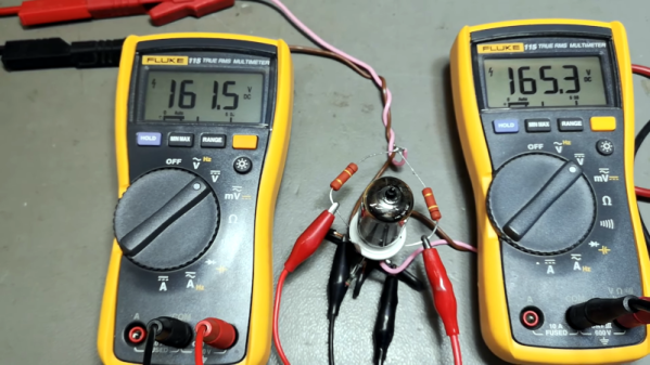
When [Thomas Scherrer] wanted to test some tubes, he made the same kind of assumption. While tubes can develop wacky failure modes, the normal difference between a working tube and a failing tube is usually not very subtle. He made a simple test rig to test tubes at DC and one operating point. Not comprehensive, but good enough most of the time. Have a look at what he did in the video below.

The tester is just a few resistors, a tube socket, and some bench power supplies. Of course, you may have to adapt it to whatever tube you are testing. If we had a lot of tubes to do, we might make the rig a bit more permanent, but for an afternoon of testing, what he has would be fine.

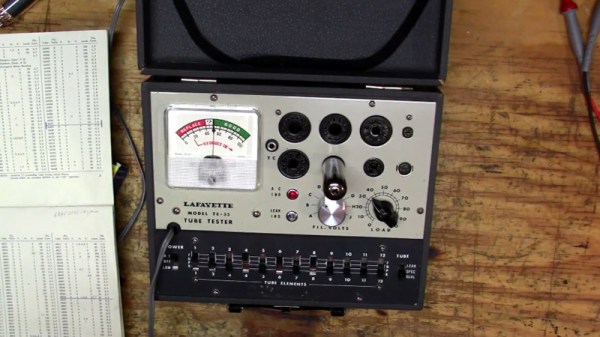
In addition to the power supplies, you’ll need at least one, preferably two, volt meters. He was able to validate his results with a proper tube tester. The results matched up well. While this won’t solve all your tube testing problems, it will give you a quick start.

You can build your own modern tube tester, of course. Or pick up a vintage one. Our favorite one uses punched cards.

Continue reading “Roll Your Own Simple Tube Tester”

The Peak Of Vacuum Tube Radio Design

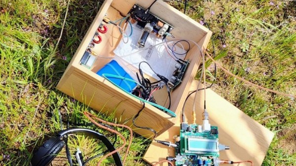
One of the more popular trends in the ham radio community right now is operating away from the shack. Parks on the Air (POTA) is an excellent way to take a mobile radio off-grid and operate in the beauty of nature, but for those who want to take their rig to more extreme locations there’s another operating award program called Summits on the Air (SOTA) that requires the radio operator to set up a station on a mountaintop instead. This often requires lightweight, low-power radios to keep weight down for the hike, and [Dan] aka [AI6XG] has created a radio from scratch to do just that.

[Dan] is also a vacuum tube and CW (continuous wave/Morse code) operator on top of his interest in summiting various mountains, so this build incorporates all of his interests. Most vacuum tubes take a lot of energy to operate, but he dug up a circuit from 1967 that uses a single tube which can operate from a 12 volt battery instead of needing mains power, thanks to some help from a more modern switch-mode power supply (SMPS). The SMPS took a bit of research, though, in order to find one that wouldn’t interfere with the radio’s operation. That plus a few other modern tweaks like a QCX interface and a switch to toggle between receive to transmit easily allows this radio to be quite versatile when operating while maintaining its portability and durability when summiting.

For those looking to replicate a tube-based radio like this one, [Dan] has made all of the schematics available on his GitHub page. The only other limitation to keep in mind with a build like this is that it tends to only work on a very narrow range of frequencies without adding further complexity to the design, in this case within the CW portion of the 40-meter band. But that’s not really a bad thing as most radios with these design principles tend to work this way. For some other examples, take a look at these antique QRP radios for operating using an absolute minimum of power.

Tube Amplifier Uses Low Voltage, Sips Battery

Much like vinyl records, tube amplifiers are still prized for their perceived sound qualities, even though both technologies have been largely replaced otherwise. The major drawback to designing around vacuum tubes, if you can find them at all, is often driving them with the large voltages they often require to heat them to the proper temperatures. There are a small handful of old tubes that need an impressively low voltage to work, though, and [J.G.] has put a few of them to work in this battery-powered audio tube amplifier.

The key to the build is the Russian-made 2SH27L battery tubes which are originally designed in Germany for high-frequency applications but can be made to work for audio amplification in a pinch. The power amplifier section also makes use of 2P29L tubes, which have similar characteristics as far as power draw is concerned. Normally, vacuum tubes rely on a resistive heater to eject electrons from a conductive surface, which can involve large amounts of power, but both of these types of tubes are designed to achieve this effect with only 2.2 volts provided to the heaters.

[J.G.] is powering this amplifier with a battery outputting 5V via a USB connection, and driving a fairly standard set of speakers borrowed from a computer. While there aren’t any audio files for us to hear, it certainly looks impressive. And, as it is getting harder and harder to find vacuum tubes nowadays, if you’re determined to build your own amplifier anyway take a look at this one which uses vacuum tubes built from scratch.

Single Photon Detection With Photomultipliers

Unless you are an audiophile, you likely think of tubes as mostly relegated to people who work on old technology. However, photomultiplier tubes are still useful compared to more modern sensors, and [Jaynes Network] has a look into how they work, especially with scintillating detectors.

The RCA photomultiplier he examines has ten stages and can detect even a single photon. Combined with a scintillating detector, they make good radiation detectors.

We can’t help but smile when we hear someone obviously in love with the engineering behind a tube like this. We get it. The inside of the tube is crowded, so it is hard to identify the dynodes and other portions, but some diagrams make it readily apparent how the tube does its job.

We were impressed with how good the documentation that came with the tube looked, considering its age. We mean the condition it was in. The document itself was obviously a reproduction of a typewritten document with hand-drawn figures and graphs.

We were hoping for some footage of the tube in action, but we’ll have to wait for a future video. We are betting that is coming, though. Although there are some solid-state detectors, they are not suitable for all applications. There was a time, though, when the tubes were in many applications, including X-ray scanners and photography equipment.

Continue reading “Single Photon Detection With Photomultipliers”

Everything You Wanted To See About Restoring A 1956 Radio

Ever wanted a good, good look at the insides of a 1950s radio, along with fantastic commentary on the internals and the purpose of various components? Then don’t miss [Adam Wilson]’s repair and restoration of a 1956 Philips 353A, a task made easier by a digitized copy of the service manual. [Adam] provides loads of great pictures, as well as tips on what it takes to bring vintage electronics back to life. What’s not to like?

Vintage electronics like this are often chock-full of components that deteriorate with age, so one doesn’t simply apply power to see if it still works as a first step. These devices need to be inspected and serviced before power is ever applied. Even then, powerup should be done with a current-controlled source that can be shut down if anything seems amiss.

Thank goodness for high quality, digitized service manuals.

Devices like these largely predate printed circuit boards, so one can expect to see plenty of point-to-point soldering. Vacuum tubes did much of the hard work, so they are present instead of integrated circuits and transistors. Capacitors in the microfarads were much larger compared to their modern equivalents, and paper/wax capacitors (literally made from rolled-up paper covered in wax) handled capacitances in the nanofarad range instead of the little ceramic disk caps of today.

One thing that helped immensely is the previously-mentioned Philips 353A service manual, which includes not only a chassis and component layout, but even has servicing procedures such as cord replacement for the tuning dial. Back then, a tuning dial was an electromechanical assembly that used a winding of cord to rotate the tuning capacitor, and replacing it was a fiddly process. If only all hardware was documented so well!

The end result looks wonderful and still has great sound. As a final tweak, [Adam] added an external audio input cable as a nod to the modern age. Now, we have in the past seen a small LED screen integrated convincingly into an antique, but in this case [Adam] kept the original look completely intact. You can see it in action, playing some Frank Sinatra in the short video embedded below.
Continue reading “Everything You Wanted To See About Restoring A 1956 Radio”

Vintage Tube Tester Teardown

[Mr. Carlson] has an old-style 1940-era radio tube tester, the kind that used to inhabit grocery and drug stores. It is in amazing condition and he was kind enough to tear it down for us. The tester is a Model X from the Radiotechnic Laboratory in Evanston Illinois and, like [Mr. Carlson], we were amused that one of the indicators on the device is a Ouija board-like “doubtful” reading. When it lights up, it looks amazing.

This is much older than the old “TV tube testers” we remember as a kid, but the idea is the same: you have a bad radio or TV with tubes in it, it is a fair bet that the problem is a tube. Even if you don’t know much about electronics, you can carefully remove the tubes, drive over to the drugstore, test your tubes and buy a replacement for any that are bad. Uniquely, this tester even had a speaker you could use to listen to the tube’s output while testing.

Continue reading “Vintage Tube Tester Teardown”

Reactive Load For Amplifiers Teaches Lessons About Inductors

The sound produced by any given electric guitar is shaped not just by the instrument itself but by the amplifiers chosen to make that sound audible. Plenty of musicians swear by the warm sound of amplifiers with vacuum tube circuits, but they do have some limitations. [Collin] wanted to build a reactive load for using tube amps without generating a huge quantity of sound, and it resulted in an interesting project that also taught him a lot about inductors.

The reactive load is essentially a dummy load for the amplifier that replaces a speaker with something that won’t produce sound. Passive loads typically use resistor banks but since this one is active, it needs a very large inductor to handle the amount of current being produced by the amplifier. [Colin] has also built a headphone output into this load which allows it to output a much smaller quantity of sound to a headset while retaining the sound and feel of the amplifier tubes, and it additionally includes a widely-used tone control circuit as well.

There’s a lot going on in the design of the circuitry for this amplifier load, including a lot of research into low-frequency inductors that can handle a significant amount of current. [Collin] eventually ended up winding his own, but the path he took to it was long and winding. There’s a lot of other circuit theory discussed as well especially with regards to the Baxandall EQ that he built into it as well. And, if you’d like to learn more about tube amplifiers in general, take a look at this piece which notes one of the best stereo amps ever produced.