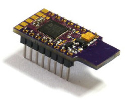
8-bit AVRs and 32-bit ARMs do one thing, and one thing well: controlling other electronics and sensors while sipping power. The Internet of Things is upon us and with that comes the need for connecting to WiFi networks. Already, a lot of chips are using repackaged System on Chips to provide an easy way to connect to WiFi, and the USR-WIFI232-T is the latest of the bunch. It’s yet another UART to WiFi bridge, and as [2XOD], it’s pretty easy to connect to an AVR.
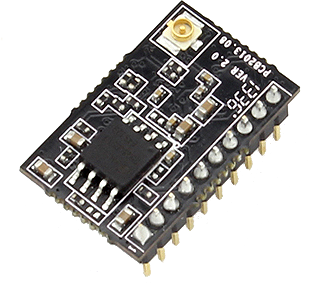
The module in question can be had through the usual channels for about $11, shipped straight from China, and the only purpose of this device is to provide a bridge between a serial port and a wireless network. They’re not that powerful, and are only meant for simple tasks,
[2XOD] got his hands on one of these modules and tested them out. They’re actually somewhat interesting, with all the configuration happening over a webpage served from the device. Of course the standard AT commands are available for setting everything up, just like the ESP8266.
With a month of testing, [2XOD] has found this to be a very reliable device, logging temperatures every minute for two weeks. There’s also a breakout board available to make connection easy, and depending on what project you’re building, these could be a reasonable stand-in for some other popular UART -> WiFi chips.