Hands On The Stellaris Launchpad

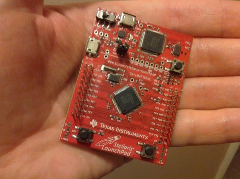
We just got our hands on a Stellaris Launchpad. We had placed an order when the preorder was originally announced, but the marketing folks at TI reached out an offered to send us one a bit sooner and took them up on it. We’ve embedded a quick unboxing video after the break but read on for some info that didn’t make it into that clip.

The look and feel of the board and its packaging are almost exactly the same as the MSP430 version of the Launchpad. But why not? After all it worked so well the first time. This board hosts an ARM Cortex-M4 processor. The two buttons on the bottom are user buttons, the one on the upper right is a reset button. The top of the board is the programmer, with a micro USB port for connectivity. The kit also includes about a 2′ cable for this connection. Next to that jack is a switch that selects a power source. You’ll also notice a USB port to the left, this because the processor includes USB functionality, with a free library available from TI. Power can come from the programmer/debugger USB port, or from this device USB port. There are dual pin headers to either side on the face of the board, and pin sockets on the back which break out pins of the processor. Just below the reset button is a RGB LED, and a clock crystal has also been populated just above the chip.

When plugged in via the programmer’s USB port the PWR LED lights up as does the RGB LED. The firmware that ships on the device fades through a range of colors and the user buttons scroll through a set of predefined colors. The device enumerates as: “Bus 002 Device 005: ID 1cbe:00fd Luminary Micro Inc.” on our machine. But if you connect it via the device USB jack it enumerates as: “Bus 001 Device 015: ID 04e8:689e Samsung Electronics Co., Ltd GT-S5670 [Galaxy Fit]”. Interesting.

We have no idea if there are programming tools for flashing the board using a Linux box, but we’ll be trying to figure it out. If you have some info please share it in the comments.

Continue reading “Hands On The Stellaris Launchpad”

Video Preview: New IOIO Prototype

We got our hands on this prototype of the new IOIO design. It’s a breakout board that makes adding hardware to an Android device pretty easy.  [Ytai Ben-Tsvi] sent it our way, and took a bit of time to explain some of the differences between this board and the original version. You can see our video preview embedded after the break.

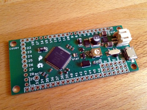
The size and form factor of the board remain the same, but the choice and layout of parts has changed. Most obviously, the USB-A connector is gone, replaced by a USB mini-B micro-B connector. This makes it possible to use the board as a USB-on-the-go device, or as a USB host device with the help of an adapter that will ship with the board. The JST connector is for external power. The previous revision included a footprint for it but it was never populated. There has also been an upgrade to the voltage regulation circuit, using a newer part as the switch-mode regulator.

There was a last-minute bug discovered in the layout. [Ytai] wants iron-clad 5V to ground short protection and is re-spinning the board to ensure he achieves that goal. He can’t say for sure, but as we mentioned in our previous post about the prototype, a price cut is planned. It could cut the current price of $50 down to just $30, but that won’t be decided until all of the choices have been made for the first production run.

Continue reading “Video Preview: New IOIO Prototype”

Drag And Drop Code Onto This ARM Dev Board

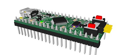
On the continuing list of homebrew ARM dev boards we’ve seen over the past few months, [Squonk42]’s USBug is one of the best we’ve seen. Like many other ARM boards, it breaks out a member of the Cortex M0/M3 family into a 40-pin DIP, but unlike all the others, [Squonk] designed it so you can drag and drop code onto the microcontroller just like a USB thumb drive.

[Squonk]’s trick relies on a certain breed of NXP LPC11xx/LPC13xx microcontrollers. These chips feature a ROM-based mass storage, meaning you can compile code on your desktop and simply shuffle it over to the USBug, no external programmer required. Here’s the relevant app note (PDF in a zip file. Double whammy).

Of course, the USBug features the I/O you’d generally expect from the current crop of Cortex-M3 devices, all while serving up 64 kB of Flash and 12 kB of RAM.

[Squonk] says he’d like to put the USBug on Kickstarter, but unfortunately he’s not a US citizen. In the spirit of Open Hardware, perhaps some maker-based electronics manufacturer will pick up where [Squonk] is forced to leave off.

Using A Raspberry Pi As Your Travel Computer

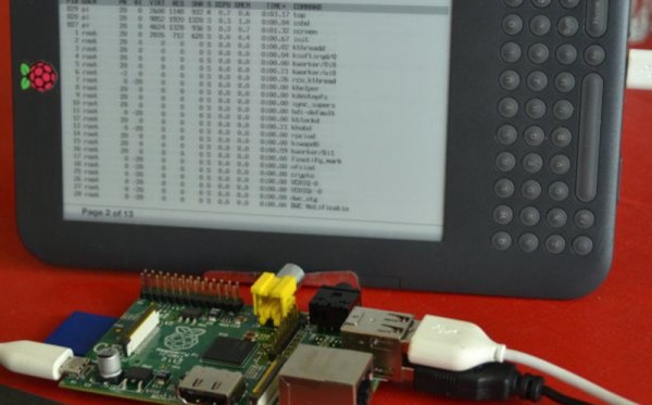
Do you think you could travel for the entire summer and leave your laptop at home? [Gef] did just that. With the help of his Kindle he used a Raspberry Pi as his travel computer. This was an easy association to think up, since he planned to bring the Kindle along as his reading material anyway. All it was going to take was some creative hacking to get it working as a display for the single-board computer.

The Kindle is merely connecting to the Raspberry Pi through a terminal emulator. This happens via USB, and requires that you Jailbreak the kindle and install a package called USBnetwork. The problem with the technique is that you’re going to go crazy trying to use the tiny keyboard that is built into the eBook reader. [Gef] decided to take a USB keyboard along with him, but how is he going to use it to control the terminal screen on the Kindle? The answer is the ‘screen’ application. We’ve used it a lot to keep programs running on a machine after we’ve exited from an SSH session. It turns out it can also be used to host multiple users on the same terminal session. Pretty neat!

[via Make]

Getting Around The Raspi’s USB Host Current Limit

For being such a revolutionary device, there are still a few problems with the Raspberry Pi. For one, the USB host ports are only able to source 140 mA per port, while the USB ports on your desktop, laptop, and even tablet are able to send a full 500 mA per port.

The official ‘fix’ for this problem is to use a powered USB port for any device that requires more than 140 mA,  something that didn’t sit well with [Manis]. He came up with an easy fix , though, that only requires a few bits of wire and a soldering iron.

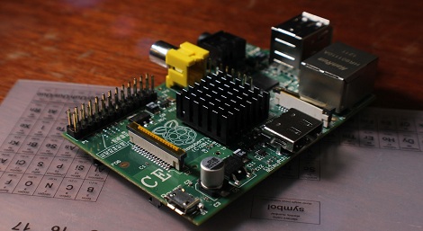
The USB ports on the Raspi are current limited to 140 mA by a pair of polyfuses. [Manis] bridged these fuses, effectively taking them out of the circuit with a short length of wire. This allowed him to use a USB hard drive (powered by USB, of course) with the Raspi.

There’s one small problem with sending that much current through the Raspi’s USB port. Sometimes, when the high-power USB device is powered on, the voltage will sag, resetting the SoC and rebooting the system. [Manis] did his homework and discovered USB 2.0-spec ports should use a 120 μF, low-ESR capacitor to prevent this. The Raspi comes stock with a 47 μF cap used for this purpose. Replacing this cap (C32) might be a good idea if you’re planning on using high-power devices with your Raspi.

Teensy Board Used As An AM Radio Transmitter

[Angus McInnes] has been working on AM radio transmission techniques. He tried out a method of using a VGA port for the task but found the vertical blanking was audible. His latest experiments use a Teensy microcontroller board as an AM transmitter.

This is not a standalone solution, but rather a hardware extension for his laptop. This is because the microprocessor doesn’t have enough cycles to do much more than read bytes over USB and push their bits out one of the I/O pins.

To get a steady stream of data he’s using isochronous mode to push a steady data stream via the USB connection. Bulk transfer is another option but [Angus] found that it caused some jitter in the audio. Each byte is fed to the AVR SPI hardware once every eight clock cycles. His transmission can be picked up from across the room, but that’s the limit since the AVR doesn’t put out that strong of a signal. But it should be a rather trivial exercise to build a simple amplifier.

PIC-based USB Conversion For An NES Controller

[Andres] wrote in to share his USB for NES controller project (translated). It enumerates as a USB keyboard and is easily mapped on most emulators. Over the weekend we looked in on an AVR programmer used for this purpose. [Andres] went a different direction, using a PIC microcontroller and eventually incorporating his circuit into the body of the controller.

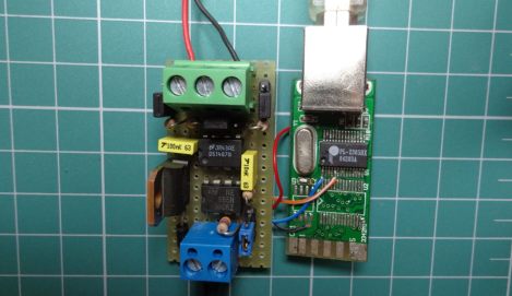
The prototype circuit can be seen above. [Andres] uses a breakout board for the PIC 18F4550 to test the circuit. The chip has native USB support, and reading the button states from the controller’s shift register is a snap. You can see him using this test rig to play Super Mario Bros. on an emulator in the video after the break.

The second iteration of the project moves from breadboard to a soldered circuit. A 18F2550 is used as it comes in a rather small DIP package. If the legs are flattened there’s room inside the controller case for it, along with a few capacitors and a crystal. The original controller cord is removed to make way for a USB cable.

Continue reading “PIC-based USB Conversion For An NES Controller”