Join us Wednesday at noon Pacific time for the ESP32 Video Tricks Hack Chat!
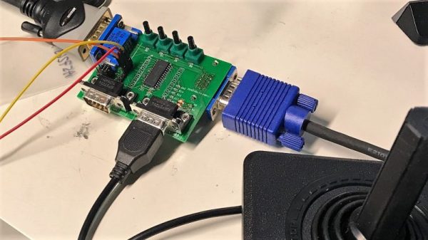
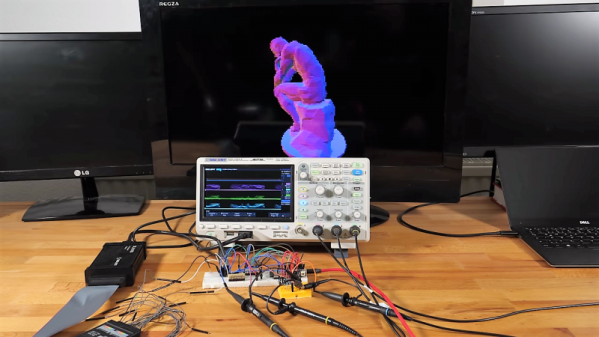
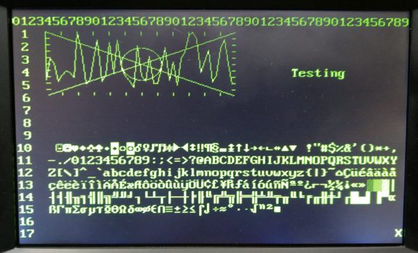
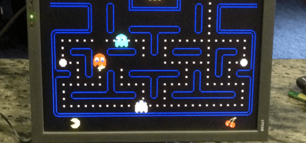
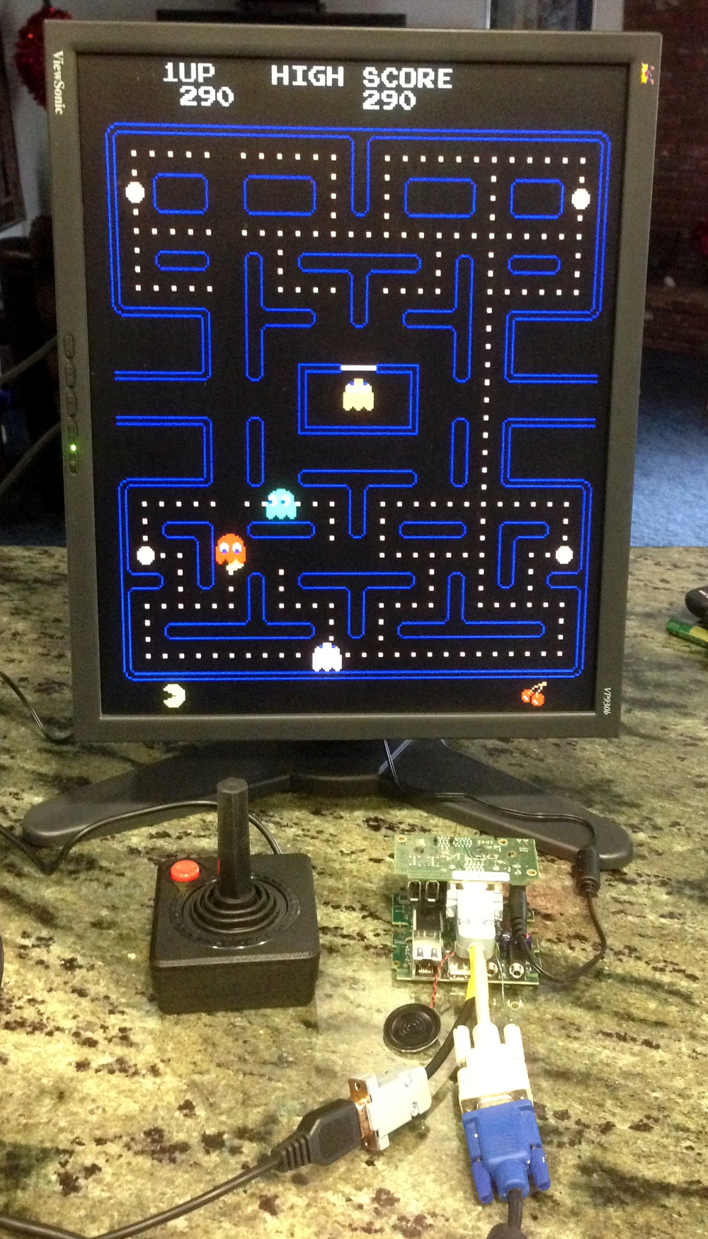
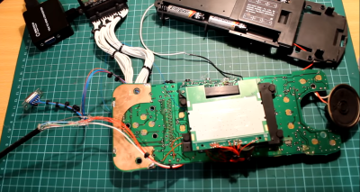
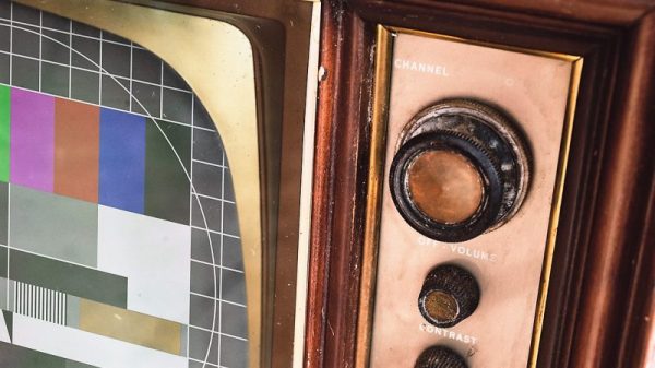
The projects that bitluni works on have made quite a few appearances on these pages over the last couple of years. Aside from what may or may not have been a street legal electric scooter, most of them have centered around making ESP32s do interesting tricks in the analog world. He’s leveraged the DACs on the chip to create an AM radio transmitter, turned an oscilloscope into a video monitor, and output composite video. That last one was handy for turning a Sony Watchman into a retro game console. He’s also found ways for the ESP32 to output VGA signals. Looks like there’s no end to what he can make the versatile microcontroller do.
Although the conversation could (and probably will) go anywhere, we’ll start with video tricks for the ESP32 and see where it goes from there. Possible topics include:
- Tricks for pushing the ESP32 DACs to their limits;
- When to use an external DAC;
- Optimizing ESP32 code by running on separate cores; and
- What about HDMI on the ESP32?
You are, of course, encouraged to add your own questions to the discussion. You can do that by leaving a comment on the ESP32 Video Tricks Hack Chat and we’ll put that in the queue for the Hack Chat discussion.
 Our Hack Chats are live community events on the Hackaday.io Hack Chat group messaging. This week we’ll be sitting down on Wednesday, March 27, at noon, Pacific time. If time zones have got you down, we have a handy time zone converter.
Click that speech bubble to the right, and you’ll be taken directly to the Hack Chat group on Hackaday.io. You don’t have to wait until Wednesday; join whenever you want and you can see what the community is talking about.