It’s that time of the year again when you gotta start worrying if you’ve been naughty enough to not receive any gifts. Hopefully, Blinky Lights will appease St. Nick. Grab a strip of RGB LEDs, hook them up to an Arduino and a Power supply, slap on some code, and Bob’s your Uncle. But if you want to retain your hacker cred, you best do it the hard way. Which is what [roddersblog] did while building his Christmas Starburst LED Stars this year — and bonus points for being early to the party.
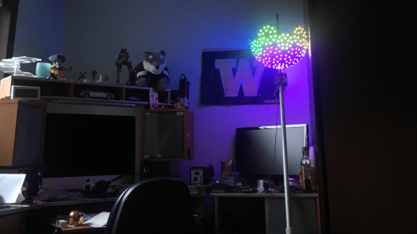
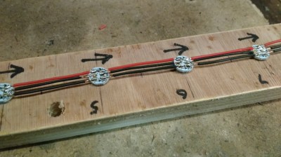 For starters, he got panels (as in PCB panels) of WS2812 boards from eBay. The advantage is it lets you choose your own pitch and strand length. The flip side is, you need to de-panel each board, mount it in a jig, and then solder three lengths of hook up wire to each LED. He planned for an eight sided star with ten LED’s each. And he built three of them. So the wiring was, substantial, to say the least. And he had to deal with silicone sealant that refused to cure and harden. But nothing that some grit and determination couldn’t fix.
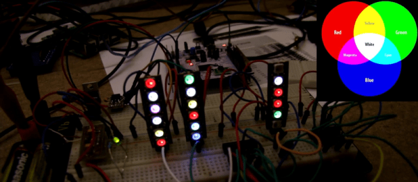
For control, he choose the PIC16F1509 microcontroller. This family has a feature that PIC calls the “Configurable Logic Cell” and this Application Note describes how to use CLC to interface the PIC to a WS2811. He noticed processing delays due to C code overheads that caused him some grief. After some experimentation, he re-wrote the entire program in assembly which produced satisfactory results. You can check out his code on the GitHub repository.
Also well worth a look, he’s got a few tricks up his sleeve to improve the quality of his home-brew PCB’s. He’s built his own UV exposure unit with timer, which is an interesting project in itself. The layout is designed in Eagle, with a flood fill to minimize the amount of copper required to be etched away. He takes a laser print of the layout, applies vegetable oil to the paper to make it more translucent to UV, and doubles up the prints to get a nice contrast.
Once the sensitized board has been exposed in the UV unit, he uses a weak but fresh and warm solution of Sodium Hydroxide as a developer to remove the unexposed UV photo-resist. To etch the board, he uses standard Feric Chloride solution, which is kept warm using an aquarium heater, while an aquarium air-pump is used to agitate the solution. He also describes how he fabricates double sided boards using the same technique. The end result is quite satisfying – check out the video after the break.
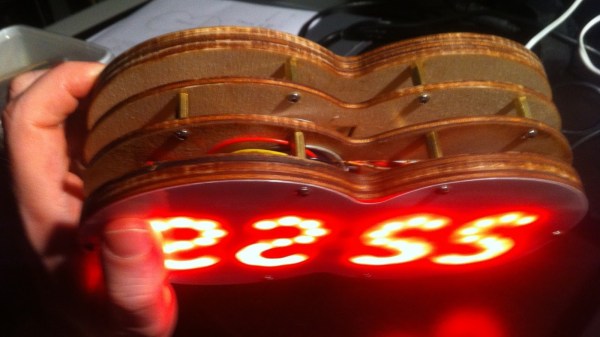
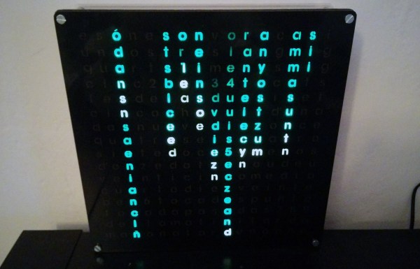
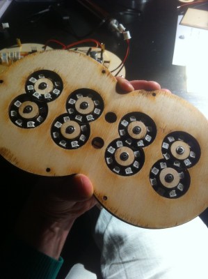 Each digit is made using one pair of Neopixel rings, stacked to form a figure of eight. All the digits are composed of arcs, so readability isn’t the best but it’s not hard either. [rhoalt] does mention that the display is easier to read via blurred camera images rather than visually, which isn’t surprising. We’re long used to seeing numbers composed of straight line segments, so arc segmented digits do look weird. But we wouldn’t have known this if [rhoalt] hadn’t shown us, right ? Maybe a thicker diffuser with separator baffles may improve the readability.