First introduced in 2002, The iRobot Roomba was conceived as a robotic vacuum cleaner. Just about every hacker, maker, and engineer out there immediately wanted one. The Roomba proved to be more than just a vacuum though; it was the perfect base for any household robotics project. Before long Roombas were being hacked to do way more than sweep your floor. iRobot recognized this, and added a hacker friendly serial port to later model Roombas. They even released a vacuumless version called the iRobot Create. Thousands of projects have literally ridden on the wheels of the Roomba. This week’s Hacklet is all about Roomba projects.
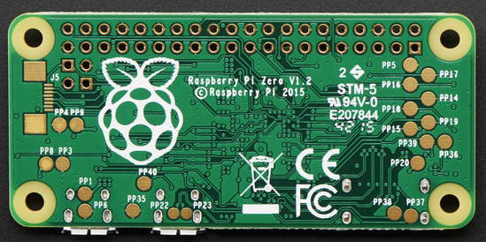
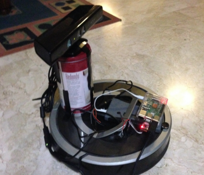 We start with [fuzzie360] and Poor Man’s Raspberry Pi Turtlebot. [Fuzzie360] has their Roomba running Robot Operating System (ROS). ROS actually is running on an on-board Raspberry Pi. While Willow Garage may be out of business, ROS lives on as an open source project run by Unbounded Robotics. Installing it can be a chore though. While [Fuzzie360] hasn’t given a full tutorial, they have offered to give advice if and when you get stuck.
A Raspberry Pi would be overkill for the simple suite of sensors built into the Roomba, but it’s perfect for [fuzzie3680’s] modified setup with a Microsoft Kinect. [Fuzzie360’s] goal is to have a robot that can vacuum the hostile territory of a university apartment.
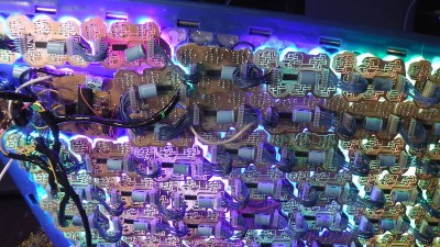
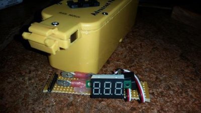 Next up is [Sircut] who upgraded his Roomba’s power cell. Early Roombas were designed to use Nickle Metal Hydride (NiMH) batteries. The individual cells are built into a proprietary iRobot battery pack. NiMH can’t hold a candle to Lithium Ion batteries though. Lithium Ion cells are very common these days in devices like cell phones and laptops. In fact, [Sircut] used 18650 sized laptop cells for this upgrade. [Sircut] also added the essential LiIon battery protection circuit to make sure those cells stay happy. A voltmeter provides a visual reference that the batteries aren’t becoming overcharged. An upgrade like this will likely double the Roomba’s runtime, but it does come at a cost. Roomba’s original charge dock can no longer be used as the on-board charge circuitry isn’t designed for LiIon battery charge algorithms.
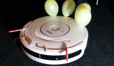 Next is [Marcel Varallo] with Robot Wars for the Commuter. How does the IT department blow off steam? Fighting robots of course! Unfortunately, [Marcel’s] coworkers aren’t all programming mavens. Hopefully some programming is in the cards for them down the road. For now though, [Marcel] has created a robot fighting league using nearly stock Roomba robots. Each bot gets a set of 3 balloons and 3 pins. A balloon represents a life. Once your lives are all popped, you’re dead! [Marcel] also created an upgrade system where winning ‘bots can move on to stronger weapons like flamethrowers. During his research, [Marcel] found out that the brushes in his Roomba are powerful enough to sweep dust and debris up without the vacuum enabled. So he’s disabled the vacuums for longer
 cleaning battle times.
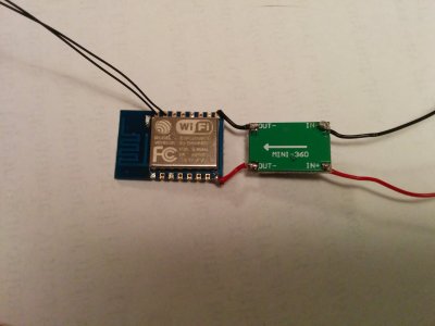 Finally we have [Fredrik Markström] and ESP8266 controlled Roomba. [Fredrick] is hacking an ESP8266 module to be the main computer of this little Robot. Of course, a ‘8266 means it will be carrying WiFi, so this robot needs to have a web interface. [Fredrik’s] first problem was powering the ESP8266. The Roomba’s battery runs around 15 volts, which is definitely not friendly to the 3.3 volt ESP8266. A switching DC to DC converter was in order, and [Fredrik] found the perfect candidate on eBay. The ‘8266 will control the Roomba through the serial interface included on all the current models. [Fredrik] has big plans for this ‘bot, including navigation and advanced vacuuming algorithms.
If you want to see more Roomba projects, check out our new Roomba project list! If I missed your project, don’t be shy, just drop me a message on Hackaday.io. That’s it for this week’s Hacklet. As always, see you next week. Same hack time, same hack channel, bringing you the best of Hackaday.io!


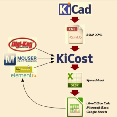 Another useful utility from [xesscorp] is