This GPS Speedometer Hangs Off Your Handlebars

If you can ride a bike with no handlebars, no handlebars, no handlebars, you can do just about anything. You can take apart a remote control, and you can almost put it back together. You can listen in on a two meter repeater and you can build a GPS module speedometer. That’s what [Jeremy Cook] did with just a few parts, a little 3D design, and some handy zip ties to hold it onto the handlebars, the handlebars.

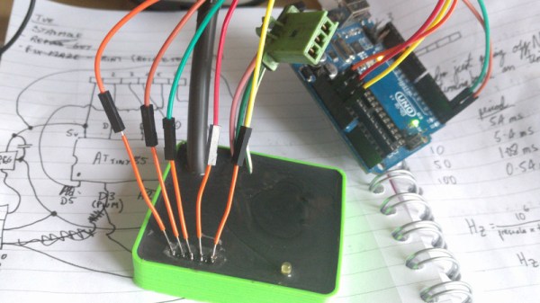
The electronics for this build are relatively simple, based on an Arduino Pro Mini because that’s just about the smallest readily available development board you’ll be able to find. To this is a LiPo, a LiPo charging circuit, a GPS module, and a single RGB LED. The code gets some data from the GPS module and figures out a speed. This is then translated into a color — red, yellow, or green depending on whether you’re stationary, below 5 km/h, or above 5 km/h.

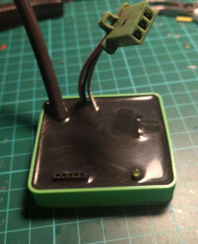
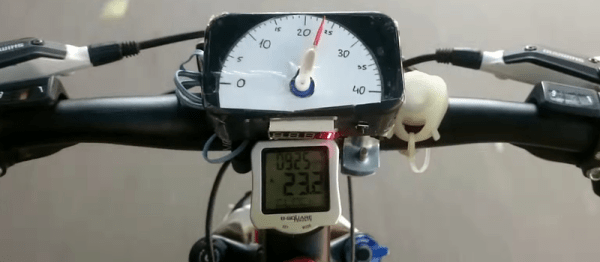
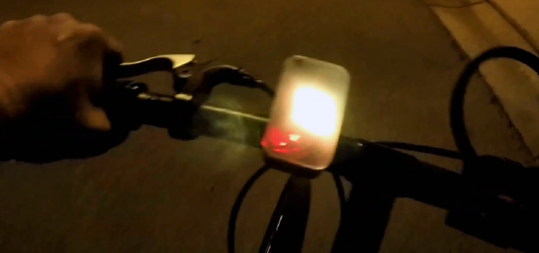
All these electronics are stuffed into a 3D-printed enclosure. The majority of the enclosure is printed in black, with a translucent top that serves as a great diffuser for the LED. Just two zip ties hold this GPS speedometer onto the handlebars, and from the video below, everything looks great. The GPS module does take some time to get data at first, but that’s a common problem with GPS units that have been powered off for a few days. If only someone made a GPS module that could keep time with no metronome, with no metronome.

Continue reading “This GPS Speedometer Hangs Off Your Handlebars”

Interfacing With A Digital Speedometer

After swapping the engine out in his scooter, [James Stanley] made an unfortunate discovery. The speedometer was digitally controlled, and while the original engine had a sensor which would generate pulses for it to interpret, his new engine didn’t. Learning that the original sensor would pull the signal wire to ground each time it detected a tooth of one of the spinning gears, [James] reasoned he needed to find a way to detect the scooter’s speed and create these pulses manually.

To find the scooter’s speed, he installed a magnet on the front wheel and a hall effect sensor on the fork to detect each time it passed by. Since the wheel is of a known circumference, timing the pulses from the sensor allows calculation of the current speed. A GPS receiver could be used if you wanted fewer wires, but the hall effect sensor on the wheel is simple and reliable. With the speed of the scooter now known, he needed to turn that into a signal the speedometer understands.

Speedometer controller potted with resin.

[James] wrote a program for an ATmega that would take the input from the wheel sensor and use it to create a PWM signal. This PWM signal drives a transistor, which alternates the speedometer sensor wire between low and floating. With a bit of experimentation, he was able to come up with an algorithm which equated wheel speed to the gearbox speed the speedometer wanted with accuracy close enough for his purposes.

While the software side of this project is interesting in its own right, the hardware is an excellent case study in producing robust electronic devices suitable for use on vehicles. [James] 3D printed a shallow case for the circuit board, and potted the entire device with black polyurethane resin. He even had the forethought to make sure he had a debugging LED and programming connector before he encapsulated everything (which ended up saving the project).

While the specific scenario encountered by [James] is unlikely to befall others, his project is an excellent example of not only interfacing with exiting electronics but producing rugged and professional looking hardware without breaking the bank. Even if scooters aren’t your thing, there are lessons to be learned from this write-up.

For all you two wheeled hackers out there, we’ve covered similar projects designed for bicycles, as well as some very slick digital speedometer mods for motorcycles.

Arduino + Geometry + Bicycle = Speedometer

It is pretty easy to go to a big box store and get a digital speedometer for your bike. Not only is that no fun, but the little digital display isn’t going to win you any hacker cred. [AlexGyver] has the answer. Using an Arduino and a servo he built a classic needle speedometer for his bike. It also has a digital display and uses a hall effect sensor to pick up the wheel speed. You can see a video of the project below.

[Alex] talks about the geometry involved, in case your high school math is well into your rear view mirror. The circumference of the wheel is the distance you’ll travel in one revolution. If you know the distance and you know the time, you know the speed and the rest is just conversions to get a numerical speed into an angle on the servo motor. The code is out on GitHub.

Continue reading “Arduino + Geometry + Bicycle = Speedometer”

Analog Guts Display GPS Velocity In This Hybrid Speedometer

A digital dash is cool and all, but analog gauges have lasting appeal. There’s something about the simplicity of a purely mechanical gauge connected directly to a vehicle’s transmission. Of course that’s not what’s hapenning here. Instead, this build is an analog display for GPS-acquired speed data.

The video below does a good job at explaining the basics of [Grant Stephens]’ build. The display itself is a gutted marine speedometer fitted with the movement from a motorcycle tachometer. The tach was designed to take a 4-volt peak-to-peak square wave input signal, the frequency of which is proportional to engine speed. To display road speed, [Grant] stuffed an ATTiny85 with a GPS module into the gauge and cooked up a script to convert the GPS velocity data into a square wave. There’s obviously some latency, and the gauge doesn’t appear to register low speeds very well, but all in all it seems to match up well to the stock speedo once you convert to metric.

There’s plenty of room for improvement, but we can see other applications where an analog representation of GPS data could be useful. And analog gauges are just plain fun to digitize – like these old meters and gauges used to display web-scraped weather data.

Continue reading “Analog Guts Display GPS Velocity In This Hybrid Speedometer”

An Internet Speedometer With A Dekatron

[Sprite_tm], like most of us, is fascinated with the earlier ways of counting and controlling electrons. At a hacker convention, he found an old Dekatron tube hooked up to a simple spinner circuit. The prescription for this neon infatuation was to build something with a Dekatron, but making another spinner circuit would be a shame. Instead, he decided to do something useful and ended up building an Internet Speedometer with this vintage display tube.

Like all antique tubes, the Dekatron requires about 400V to glow. After a bit of Googling, [Sprite] found a project that drives a Dekatron with an AVR with the help of a boost converter. Borrowing the idea of controlling a boost converter with a microcontroller, [Sprite] built a circuit with the Internet’s favorite Internet of Things thing – the ESP8266 – that requires only a 12 volt wall wart and a handful of parts.

Controlling the rotating glow of a Dekatron is only half of the build; this device is an Internet speedometer, too. To read out his Internet speed, [Sprite] is using a managed switch that allows SNMP to read the number of incoming and outgoing octets on a network interface. By writing a simple SNMP client for the ESP8266, the device can read how clogged the Intertubes are, both incoming and outgoing.

With an acrylic case fresh out of the laser cutter and a remarkably good job at bending acrylic with a heat gun, [Sprite] has a tiny device that tells him how much Internet he’s currently using. He has a video of it running a speedtest, you can check that video out below.

Continue reading “An Internet Speedometer With A Dekatron”

Nixie Tube Speedometer In Motorcycle Handlebars

The handlebars of this Honda CL175 ended up being perfect for holding two Nixie tubes which serve as the speedometer. There are two circular cavities on the front fork tree which are the same size as the Nixies. Wrapping the tubes in a bit of rubber before the installation has them looking like they are factory installed!

This isn’t a retrofit, he’s added the entire system himself. It starts with a hall effect sensor and magnets on the rear wheel and swing arm. Right now the result is 4 MPH resolution but he plans to add more magnets to improve upon that. For now, the driver and speedometer circuitry are hosted on protoboard but we found a reddit thread where [Johnathan] talks about creating a more compact PCB. If your own bike lacks the fork tree openings for this (or you need help with the drivers) check out this other Nixie build for a slick-looking enclosure idea.

The link at the top is a garage demo, but last night he also uploaded a rolling test to show the speedometer in action. Check out both videos after the break.

Continue reading “Nixie Tube Speedometer In Motorcycle Handlebars”

Website Response Speedometer

Here’s something that will probably make it to a wall right next to the people responsible for the Hackaday servers sometime soon, and should be something every web dev should build at some point: a website response meter, an analog gauge that will tell you how long it takes to reach your website.

The build is simple enough, with a micro servo working as a gigantic analog gauge. There are also a pair of four-digit, seven-segment displays for displaying a digital number and the number of website requests per second. There’s also an 8×8 matrix of bi-color LEDs for showing a green happy face or a red frowny face, just in case all that data wasn’t self-evident to the uninitiated.

All the electronics are handled by an Arduino, but what really makes this build useful, or even possible, is the bit of code that runs on a computer. The computer uses an API from New Relic, a software analytics company, to come up with the response time and requests per second. That data is pulled down and piped up to the Arduino that displays everything on a beautifully milled acrylic sheet.