WS2812 at 670 kHz

Driving WS2812B Pixels, With DMA Based SPI

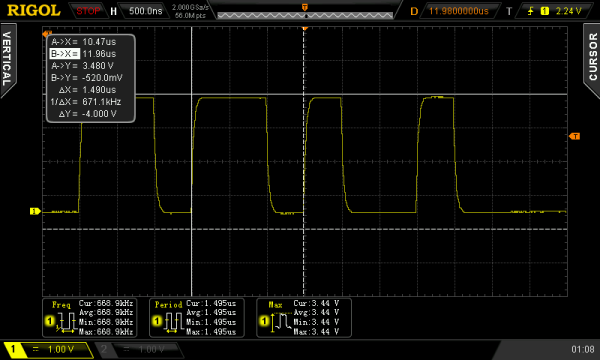
Typically bit-banging an I/O line is the common method of driving the WS2812B (WS2811) RGB LEDs. However, this ties up precious microcontroller cycles while it waits around to flip a bit. A less processor intensive method is to use one of the built-in Serial Peripheral Interface (SPI) modules. This is done using specially crafted data and baud rate settings, that when shifted out over the Serial Data Out (SDO) pin, recreate the needed WS2812B signal timing. Even when running in SPI mode, your hardware TX buffer size will limit how many pixels you can update without CPU intervention.

[Henrik] gets around this limitation by using peripheral DMA (Direct Memory Access) to the SPI module in the Microchip PIC32MX250F128B microcontroller. Once properly configured, the DMA controller will auto increment through the defined section of DMA RAM, sending the pixel data over to the SPI module. Since the DMA controller takes care of the transfer, the micro is free to do other things. This makes all of DMA memory your display buffer. And leaves plenty of precious microcontroller cycles available to calculate what patterns you want the RGB LEDs to display.

Source code is available at the above link for those who would like to peruse, or try it out. This is part of [Henrik’s] Pixel Art Project. Video of DMA based SPI pixels after the break:

Continue reading “Driving WS2812B Pixels, With DMA Based SPI”

Green Lights Forever

Green Light Your Commute With America’s Unsecured Traffic Lights

Remember that episode of Leverage (season 5, episode 3), where Alec uses Marvin to wirelessly change all the street lights green so they can catch up to an SUV? And you scoffed and said “that’s so not real!”… well actually they got it right. A new study out of the University of Michigan (PDF warning), shows just how easy it is to make your morning commute green lights all the way.

The study points out that a large portion of traffic lights in the United States communicate with each other wirelessly over the 900Mhz and 5.8Ghz ISM band with absolutely no encryption. In order to connect to the 5.8Ghz traffic signals, you simply need the SSID (which is set to broadcast) and the proper protocol. In the study the researchers used a wireless card that is not available to the public, but they do point out that with a bit of social engineering you could probably get one. Another route is the HackRF SDR, which could be used to both sniff and transmit the required protocol. Once connected to the network you will need the default username and password, which can be found on the traffic light manufacturer’s website. To gain access to the 900Mhz networks you need all of the above and a 16-bit slave ID. This can be brute forced, and as the study shows, no ID was greater than 100. Now you have full access, not to just one traffic signal, but EVERY signal connected to the network.

Once on the network you have two options. The completely open debug port in the VxWorks OS which allows you to read-modify-write any memory register. Or by sending a(n) UDP packet where the last byte encodes the button pressed on the controller’s keypad. Using the remote keypad you can freeze the current intersection state, modify the signal timing, or change the state of any light. However the hardware Malfunction Management Unit (MMU) will still detect any illegal states (conflicting green or yellow lights), and take over with the familiar 4-way red flashing. Since a technician will have to come out and manually reset the traffic signal to recover from an illegal state, you could turn every intersection on the network into a 4-way stop.

So the next time you stop at a red light, and it seems to take forever to change, keep an eye out for the hacker who just green lit their commute.

Thanks for the tip [Matt]

PID balancing a ball on a plate

Stewart Platform Ball Bearing Balancer

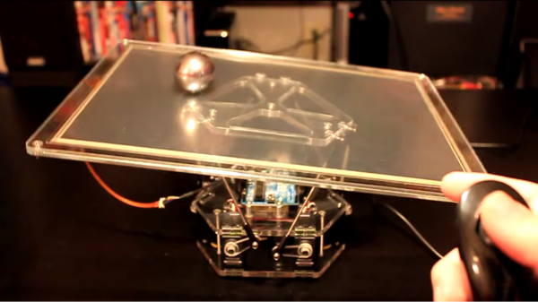
For their Mechanical Engineering senior design project at San Jose State University, [Tyler Kroymann] and [Robert Dee] designed and built a racing motion simulator. Which is slightly out of the budget of most hackers, so before they went full-scale, a more affordable Arduino powered Stewart platform proof of concept was built. Stewart platforms typically use six electric or hydraulic linear actuators to provide motion in six degrees of freedom (6 DOF), surge (X), sway (Y), heave (Z), pitch, roll, and yaw. With a simple software translation matrix, to account for the angular displacement of the servo arm, you can transform the needed linear motions into PWM signals for standard hobby servos.

The 6 DOF platform, with the addition of a resistive touch screen, also doubled as a side project for their mechatronic control systems class. However, in this configuration the platform was constrained to just pitch and roll. The Arduino reads the resistive touch screen and registers the ball bearing’s location. Then a PID compares this to the target location generating an error vector. The error vector is used to find an inverse kinematic solution which causes the actuators to move the ball towards the target location. This whole process is repeated 50 times a second. The target location can be a pre-programmed or controlled using the analog stick on a Wii nunchuck.

Watch the ball bearing seek the target location after the break.

Thanks to [Toby] for sending in this tip.

Continue reading “Stewart Platform Ball Bearing Balancer”

Build An Efficient Inverter, Win A Million Dollars

Little Box Challenge

Google and the IEEE are giving away a million dollar prize to an individual or team, that can build the most efficient and compact DC to AC inverter. The goal is to design and build a 2kW inverter with a power density greater than 50W per cubic inch. To put that in perspective, conventional solar string inverters have power densities around 0.5-3W per cubic Inch, and microinverters around 5W per cubic Inch. So in other words, an order of magnitude more efficient than what we have now.

For the challenge, the inverter needs to convert 450VDC, with a 10 ohm series resistor simulating a solar array, to 240VAC @ 60Hz. Testing will consist of powering various resistive, inductive and capacitive loads ranging from 0-2kVA. The inverter is expected to regulate voltage within 5%, and frequency within 0.05%, while keeping the enclosure below 60 degrees C, and conforming to FCC Part 15 B (Unintentional radiators).

If you and/or your team can figure out the most efficient topology, switching frequency, novel use of high power wide bandgap (WBG) semiconductors, physically reduce the size of the input and output filters, and keep the whole thing running cool. Then get registered before the September 30, 2014 deadline. Inverters need to be functional and the results of this test procedure (PDF warning) sent in before July 22, 2015, then 18 finalists will be chosen to bring their inverters in person to a testing facility in the United States by October 21, 2015. The grand prize winner will be announced sometime in January, 2016

[Thanks for the tip Dmytro]

This Arduino power inverter would need a serious upgrade to enter. And speaking of entering challenges, it’s still not too late to enter our very own Hackaday Prize!

Home Theater, Tribute To A Friend

The Greg Williams Theater

Ever since purchasing this house, [Ed] Always wanted a to turn his living room into a home theater, but not just any old projector and a white wall would do. He wanted the whole experience. [Ed] Started with a slightly damaged 12′ wide 4:3 roll up projector screen, he removed the damaged bottom portion and built a static frame to support the now 16:9 screen. Before he could mount the screen, he needed to drywall over a window that was inconveniently located. With the screen now in place, [Ed] framed out the elevated seating platform and steps with some 2×12 topped off with plywood. Next, the carpet that was sitting directly below the platform and steps was removed and then secured on top. Down firing LED fixtures were installed in the steps, to give them that movie theater look and feel. To provide the image, a refurbished HD projector acquired from the Bay of Electronics, was installed in the loft above the living room.

With the theater functional, [Ed] turned his attention to theater decorations. Dimmable ambiance lighting fixtures, using laser cut acrylic and CNC routed starboard (a marine-grade polymer), were made to resemble a film strip. Next a coffee table was crafted out of an equipment road case filled with movie props. Studio logos were painted on the sides with the use of laser cut stencils, and with a glass top, gives the illusion it came off the set of a hollywood movie. The addition of a rebuilt movie poster marquee, movie posters, candy stand, pop corn machine, and with the existing soda fountain and the arcade in the loft, the home theater was almost complete.

In a fitting tribute, [Ed] designed and built a marquee sign to dedicate and name the theater after his cousin Greg, one of his closest friends and avid movie watcher, who had sadly passed away. Video overview of all the hard work after the break.

Continue reading “Home Theater, Tribute To A Friend”

Arduino SPI Library Gains Transaction Support

Transaction SPI Timing

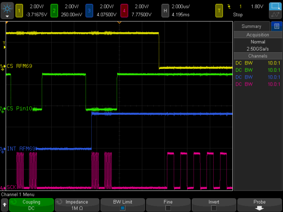
To prevent data corruption when using multiple SPI devices on the same bus, care must be taken to ensure that they are only accessed from within the main loop, or from the interrupt routine, never both. Data corruption can happen when one device is chip selected in the main loop, and then during that transfer an interrupt occurs, chip selecting another device. The original device now gets incorrect data.

For the last several weeks, [Paul] has been working on a new Arduino SPI library, to solve these types of conflicts. In the above scenario, the new library will generate a blocking SPI transaction, thus allowing the first main loop SPI transfer to complete, before attempting the second transfer. This is illustrated in the picture above, the blue trace rising edge is when the interrupt occurred, during the green trace chip select. The best part, it only affects SPI, your other interrupts will still happen on time. No servo jitter!

This is just one of the new library features, check out the link above for the rest. [Paul] sums it up best: “protects your SPI access from other interrupt-based libraries, and guarantees correct setting while you use the SPI bus”.