Turning A Microchip MPLAB Snap Into A UDPI AVR Programmer

The Unified Program and Debug Interface (UPDI) is Microchip’s proprietary interface for programming and on-chip debugging, and has become the standard on AVR MCUs after Microchip’s purchase of Atmel. Being a proprietary interface means that even entry-level programmers like the Atmel-ICE are rather expensive at over $100. That’s when for [Scott W Harden] the question arose of whether the much cheaper MPLAB Snap board (~$34) could be used as well for AVR UDPI purposes.

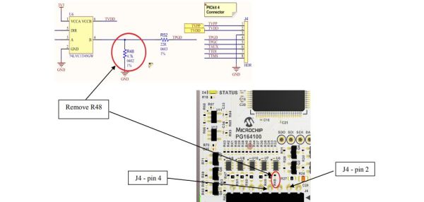
The stages of grief that [Scott] went through before he had it working involved among others the updating of the MPLAB Snap board firmware, getting yelled at by the Microchip Studio IDE when attempting to use the Snap for AVR MCU programming, and ultimately fixing the board following the relevant Microchip Engineering Technical Note (ETN #36) that specifies the removal of a 4.7 kΩ pull-down resistor (R48) on the Snap board. This allows the UDPI line to be pulled high by the MCU.

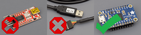
As the ETN notes, an external pull-up may also be used to override the pull-down, which would leave the ICSP functionality of of the Snap intact. As [Scott] mentions in his conclusion, it feels as if UDPI AVR support with the Snap is really an afterthought for Microchip. Meanwhile there are also more DIY solutions as [Scott] adds, which are useful for just flashing the MCU. An example is with a USB-TTL serial adapter and pymcuprog.

The problem with DIY solutions like jtag2updi, ftdi2updi, and their kin is the effort required to assemble them, and the uncertainty of long-term support as the UPDI ecosystem keeps evolving with new devices and new features. The MPLAB Snap with resistor mod may be just that middle ground between an Atmel-ICE and reverse-engineered OSS projects.

(Featured image: MPLAB Snap resistor mod illustrated, from Microchip ETN #36)

Knowing The Bits And Bytes That Make Images Live In Memory

We know we’re living in the future because there’s hi-resolution, full color images plastered on every high-density screen in sight. Of course this comes at a cost, one that’s been hidden away by the myriad improvements in the way we digitally represent those pretty pixels and how we push them to the screens. Nobody thinks about this, except those who are working behind the screen to store and light up those pixels. And hey, chances are that’ll be you some day. Time to learn a bit more about image encoding!

Test renders illustrate the time savings from premultiplied alpha formats

[Scott W Harden] put together a succinct primer on representing images in memory. It focuses on the basics of how images are stored: generally with the B before the G, sometimes including an alpha (transparent) channel, and with a number of different bit depths. Having these at the front of your mind is crucial for microcontroller projects, where deciding what types of images to support is often limited by the amount of memory available for frame buffers, and the capabilities of the screen chosen as the device’s display.

Speaking of display specifics, [Scott] shares some detail about mapping the memory to the dimensions of your screen. If the byte count of pixel data doesn’t line up nicely with the dimensions of the screen, padding the rows out may help in the processing overhead it takes to get those pixels onto the screen. He also has some tips about “premultiplied alpha” which makes the transparency calculation a part of the image itself, rather than demanding this be done when trying to update the screen. Running a test in C# on one million frame renders shows the type of savings you can expect.

Decades of trial and error landed us with these schemes. Looking back is literally an archaeology project, as one hacker discovered when trying to get a set of digital images off of a floppy from a 1990s photo processing service.

Sound Card ADCs For Electrocardiograms

Every few years, or so we’re told, [Scott] revisits the idea of building an electrocardiogram machine. This is just a small box with three electrodes. Attach them to your chest, and you get a neat readout of your heartbeat. This is a project that has been done to death, but [Scott]’s most recent implementation is fantastic. It’s cheap, relying on the almost absurd capability for analog to digital conversion found in every sound card, and the software is great. It’s the fit and finish that makes this project shine.

The hardware for this build is simply an AD8232, a chip designed to be the front end of any electrocardiogram. This is then simply connected to the microphone port of a sound card through a 1/8″ cable. For the exceptionally clever, there’s a version based on an op-amp. It’s an extraordinarily simple build, but as with all simple builds the real trick is in the software. That’s where this project really shines, with custom software with graphics, and enough information being displayed to actually tell you something.

We’ve seen a number of sound card ADCs being used for electrocardiograms in the past, including some from the Before Times; it makes sense, sound cards are the cheapest way to get a lot of analog data very quickly. You can check out [Scott]’s demo video out below.

Continue reading “Sound Card ADCs For Electrocardiograms”

Silicon Bugs In The FTDI FT232R, And A Tidy RF VCO Project

[Scott Harden] wrote in to tell us of some success he’s having using the FT232 chip to speak SPI directly from his laptop to a AD98850 digital signal generator. At least that was his destination. But as so often in life, more than half the fun was getting there, finding some still-unsolved silicon bugs, and (after simply swapping chips for one that works) potting it with hot glue, putting it in a nice box, and putting it up on the shelf.

In principle, the FTDI FT232 series of chips has a bit-bang mode that allows you to control the individual pins from a fairly simple API on your target computer, using their drivers and without installing anything on basically any platform. We wrote this feature up way back in 2009, and [Scott] was asking himself why he doesn’t see more hacks taking advantage of bit-bang mode.

“Square” waves

Then he answered his own question the hard way, by spending hours “debugging” his code until he stumbled on the FTDI errata note (PDF), where they admit that bit-bang mode doesn’t get timings right at all on the FT232R and FT232RL parts. FTDI has made claims that they fixed the bug in subsequent chip revisions, but the community has not been able to confirm it. If you want to use bit-bang mode, which is plenty cool, steer clear of the FT232R chips — the ones found in the ever-popular FTDI cables and many adapter dongles.

The good news here is twofold. First, now you know. Second, bit-bang mode is tremendously useful and it works with other chips from the vendor. Particularly, the FT232H and FT230X chips work just fine, among others. And [Scott] got his command-line controlled digital VCO up and running. All’s well that ends well?

We’ll wrap up with questions for the comment section. Do other manufacturers’ cheap USB-serial chips have an easily accessible bit-bang mode? Are any of you using USB bit-bang anyway? If so, what for?

Need A Night-Light?

[Scott] created an LED candle in preparation for the big mac daddy storm (storms?) coming through.  Like millions of other people in Florida, he was stuck at home with his roommates when an oncoming hurricane headed their way.  Worrying about blundering about in the dark when the power inevitably went out, they set off to gather up all of the candles they had lying around.  Realizing the monstrous pile of candles and matches looked more and more like a death wish, the decision was made to create a makeshift light out of what components they had on hand.  Now, not having access to any outside sources for parts means that you are going to have a bare bones model.

That being said, this straightforward light only takes a couple of seconds to put together.  Jury rig a couple of AA or AAA batteries up, then slap on a resistor, LED, and jumper to get that sucker running.  Wrap electrical tape around the whole thing, or even try duct tape, whatever gets the job done.  A little paper hat on top of it will diffuse the light and bada bing, bada boom, you’re all done.  Generally though, soldering directly onto a battery is not a wise idea.  So, if you want to get fancy, perhaps a better alternative is to have a battery casing as shown below.

This LED candle is a clear option if your home isn’t a micro warehouse for electronic components (apparently it is frowned upon to clog up your garage for projects), and you have limited time.  However, if you have a number of extra minutes lying around before your windows blow in, see if you can top the brightest flashlight ever made (thus far).  Continue reading “Need A Night-Light?”

RADAR Controlled Speakers

[Scott] had a simple problem – he was tired of leaning over his work bench to change the volume on his speakers. He desired a system that would readily allow him to switch the speakers on and off from a more comfortable distance. Not one to settle for the more conventional solutions available, [Scott] whipped up a RADAR-activated switch for his speaker system.

The build relies on a surprisingly cost-effective RADAR module available off the shelf, running in the 5.8GHz spectrum. At under $10, it’s no big deal to throw one of these into a project that requires some basic distance sensing. [Scott] decided to keep things simple – instead of going with a full-fat microcontroller to control the speakers, a 74HC590 IC was used to create a latch. Each time the RADAR module senses an object in close proximity, it toggles the state of the latch. The latch then controls a transistor that switches the power for the speakers.

Overall it’s a build that combines a modern integrated RADAR module with some very simple control logic to create a functional build. Of course, there’s so much more you can do with some 74-series logic. Video after the break.

Continue reading “RADAR Controlled Speakers”

Precision Pressure In A Piston

[Scott] is building a DIY yeast reactor for his aquarium. What’s a yeast reactor? [Scott] wants to pump carbon dioxide into his aquarium so his aquatic plants grow more. He’s doing this with a gallon of sugary, yeasty water bubbling into a tank of plants and fish. In other words, [Scott] is doing this whole thing completely backward and utilizing the wrong waste product of the yeast metabolism.

However, along the way to pumping carbon dioxide into his aquarium, [Scott] created a very high precision pressure sensor. It’s based on a breakout board featuring the MS5611 air pressure sensor. This has a 24-bit ADC on board, which translates into one ten-thousandths of a pound per square inch of pressure.

To integrate this pressure sensor into the aquarium/unbrewery setup, [Scott] created a pressure meter out of a syringe. With the plunger end of this syringe encased in epoxy and the pointy end still able to accept needles, [Scott] is able to easily plug this sensor into his yeast reactor. The data from the sensor is accessible over I2C, and a simple circuit with an ATmega328 and a character LCD displays the current pressure in the syringe.

We’ve seen these high-resolution pressure sensors used in drones and rockets as altimeters before, but never as a pressure gauge. This, though, is a cheap and novel solution for measuring pressures between a vacuum and a bit over one atmosphere.

Continue reading “Precision Pressure In A Piston”