Bus Pirate Commandeers I2C

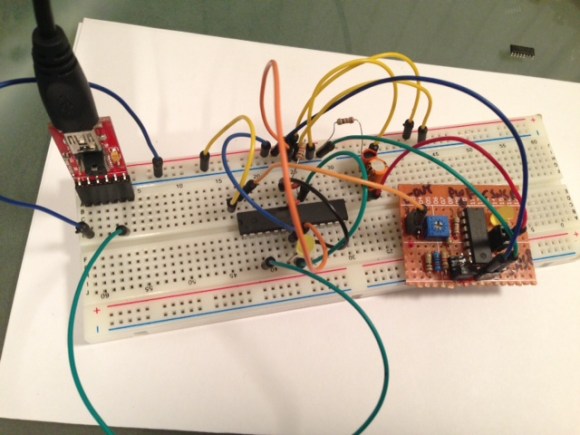
The Bus Pirate is one of our favorite tool for quick-and-dirty debugging in the microcontroller world. Essentially it makes it easy to communicate with a wide variety of different chips via a serial terminal regardless of the type of bus that the microcontroller uses. Although it was intended as a time-saving prototyping device, there are a lot of real-world applications where a Bus Pirate can be employed full-time, as [Scott] shows us with his Bus Pirate data logger.

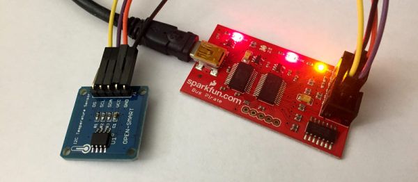
[Scott] needed to constantly measure temperature, and the parts he had on hand included an LM75A breakout board that has a temperature sensor on board. These boards communicate with I2C, so it was relatively straightforward to gather data from the serial terminal. From there, [Scott] uses a Python script to automate the process of gathering the data. The process he uses to set everything up using a Raspberry Pi is available on the project site, including the code that he used in the project.

[Scott] has already used this device for a variety of different projects around his house and it has already proven incredibly useful. If you don’t already have a Bus Pirate lying around there are a few other ways to gather temperature data, but if you have an extra one around or you were thinking about purchasing one, then [Scott]’s project is a great illustration of the versatility of this device.

Panel Meter-To-Bluetooth Hack Hijacks The Display Segments

There are a proliferation of cheap digital meter modules available online for pocket money prices. Current, voltage, frequency, or combinations thereof can all be yours for just a few dollars and a wait for shipping. Unfortunately though these meters are all self-contained units. They do not have a serial port or other interface through which you can log their readings.

This failing was not an obstacle for [Scott Harden], though. He simply added a Bluetooth interface to his combined voltage and current meter module by using an ATmega328 microcontroller to capture the signals sent to the module’s display LEDs and interpret them into readings for his Bluetooth module. He details the process of reverse engineering the meter, and his build. The result is an intriguing mess of wires with a DIP ATmega hanging on their ends. But it performs the task requested of it admirably and when mounted in a project box you would not know what lurks within.

He has made his code for the project available in his GitHub repository, we can see that this could be a valuable technique for use with other similar displays. In the video below the break he gives us a full run-down, as if his comprehensive write-up was not enough.

Continue reading “Panel Meter-To-Bluetooth Hack Hijacks The Display Segments”

Very Simple PC Frequency Counter Works Up To 100MHz

We all use 74 logic in our projects as general purpose logic interfacing glue. These chips have become as ubiquitous as a general-purpose op-amp, or even as passive components. In most cases we’re not demanding much of them, and power requirements aside an original 74 chip from the dawn of the series could probably do the same job that we’re putting a more modern variant to work on.

It is easy therefore to forget that 74 logic is a field that has seen continuous improvement and innovation reflecting the developments elsewhere in electronics, and the most modern 74 versions hide some impressively high specifications.

A good example comes via a project from [Scott, AJ4VD], a very simple frequency counter that uses a single 74 series chip at its business end, and counts to over 100MHz. The chip in question is a 74LV8154 dual 16-bit counter which he is using as a prescaler to deliver a rate more acceptable to an ATMega328 microcontroller that does the counting. As he points out, the accuracy of a frequency counter is only as good as its gate timing, and he ensures as accurate a seconds-worth of pulses as he can with a 1PPS signal derived from an inexpensive GPS receiver. The 328 makes its counting available to a host computer via a serial port, and can be easily read through a terminal. He’s built it dead-bug style on a piece of unetched PCB, on which the simplicity of the circuit is evident.

There was a time when a project like this one would have required multiple integrated circuits including a probably quite expensive purpose-built prescaler. Cheap glue logic has now advanced to a stage at which it can be done instead at commodity prices, and we like that.

We’ve featured a few 74-series counters before, including this old-school one and this one also using a 74LV8154.

The Quest For Mice With Frickin’ Laser Beams (Pointed At Their Brains), Building A Laser Controller

The logo for the field is kind of cute though.

[Scott Harden] is working on a research project involving optogenetics. From what we were able to piece together optogenetics is like this: someone genetically modifies a mouse to have cell behaviors which can activated by light sensitive proteins. The mice then have a frikin’ lasers mounted on their heads, but pointing inwards towards their brains not out towards Mr. Bond’s.

Naturally, to make any guesses about the resulting output behavior from the mouse the input light has to be very controlled and exact. [Scott] had a laser and he had a driver, but he didn’t have a controller to fire the pulses. To make things more difficult, the research was already underway and the controller had to be built

The expensive laser driver had a bizarre output of maybe positive 28 volts or, perhaps, negative 28 volts… at eight amps. It was an industry standard in a very small industry. He didn’t have a really good way to measure or verify this without either destroying his measuring equipment or the laser driver. So he decided to just build a voltage-agnostic input on his controller. As a bonus the opto-isolated input would protect the expensive controller.

The kind of travesty that can occur when [Stefan Kiese] doesn't have access to nice project boxes.
The kind of travesty that can occur when [Scott] doesn’t have access to nice project boxes.
The output is handled by an ATtiny85. He admits that a 555 circuit could generate the signal he needed, but to get a precision pulse it was easier to just hook up a microcontroller to a crystal and know that it’s 100% correct. Otherwise he’d have to spend all day with an oscilloscope fiddling with potentiometers. Only a few Hackaday readers relish the thought as a relaxing Sunday afternoon.

He packaged everything in a nice project box. He keeps them on hand to prevent him from building circuits on whatever he can find. Adding some tricks from the ham-radio hobby made the box look very professional. He was pleased and surprised to find that the box worked on his first try.

Crystal Oven Temperature Sensor Reads 0.01F Resolution

crystal-oven-temperature-sensor

[Scott Harden] continues his work on a high precision crystal oven. Being able to set a precise temperature depends on the ability to measure temperature with precision as well. That’s where this circuit comes in. It’s based around an LM335 linear temperature sensor. He’s designed support circuitry that can read temperature with hundredth-of-a-degree resolution.

Reading the sensor directly with an AVR microcontroller’s Analog-to-Digital Converter (ADC) will only yield about 1-2 degrees of range. He approached the problem by amplifying the output of the sensor to target a specific range. For the demonstration he adjusts the swing from 0-5V to correspond to a room temperature to body temperature range.

Of course he’s using analog circuitry to make this happen. But before our digital-only readers click away you should view his video explanation. This exhibits the base functionality of OpAmps. And we think [Scott] did a great job of presenting the concepts by providing a clear and readable schematic and explaining each part slowly and completely.

So what’s this crystal oven we mentioned? It’s a radio project that goes back several years.

Continue reading “Crystal Oven Temperature Sensor Reads 0.01F Resolution”

Wireless Microcontroller/PC Interface For $3

uc

Sending data from a microcontroller to a PC usually requires some sort of serial connection, either through fiddly on-chip USB, FTDI chips, or expensive radio ICs. [Scott] didn’t want to deal with this when creating a network of wireless temperature sensors, so he hacked up a few cheap 433 MHz radio transmitters and receivers to transmit data to a PC for about $3.

After sensor data is collected on a microcontroller and sent over radio, there’s still the issue of getting it into a PC. For this, [Scott] piped the data into the microphone port of a cheap USB sound card. We’ve seen this trick before both in the world of microcontrollers and loading programs onto a Commodore 64 via a cassette interface.

Once the data is sent into the sound card, it’s decoded with a a small Python app. Given the range and quality of the RF transmitters and receivers  [Scott] says it’s not an extremely reliable way to send data to a PC. It is cheap, though, and if you need to read sensors wirelessly on a budget, it’s hard to do much better.

Check out [Scott]’s demo of his creation below.

[youtube=http://www.youtube.com/watch?v=GJHFldPwZvM&w=580]

Pulse Oximeter From LM324, LED, And Photodiode

This pulse oximeter is so simple and cheap to build it’s almost criminal. The most obvious way to monitor the output of the sensor is to use an oscilloscope. The poor-man’s stand-in for that is a sound card, which is what [Scott Harden] demonstrates in his write-up.

It uses a concept we’ve seen a few times before. The light from an LED shines through your finger and is measured on the other side by a phototransistor. It’s that light grey plastic thing you see on a patient’s finger when they’re in the hospital. [Scott] went with a common wooden clothes pin as a way to mount and align the sensor with your finger. It is monitored by the simplest of circuits which uses just one chip: an LM324 op-amp. There are three basic stages which he explains well in the video after the jump. The incoming signal is decoupled before being fed to the first amplifier stage. From there it is fed to an adjustable low-pass filter to help eliminate 60Hz noise from AC power in the room. The last stage amplifies the signal again while using another low-pass filter in parallel.

Continue reading “Pulse Oximeter From LM324, LED, And Photodiode”