Why Is My 470uF Electrolytic Cap More Like 20uF?

The simple capacitor equivalent circuit taught in school

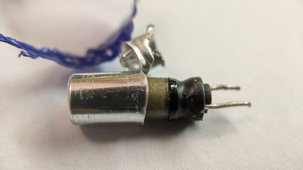
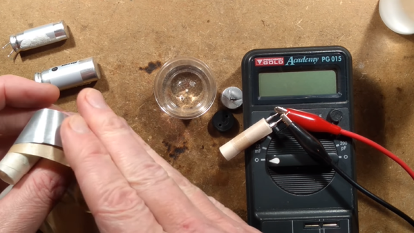
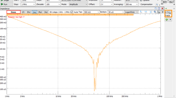
Inductors are more like a resistor in series with an ideal inductor, resistors can be inductors as well, and well, capacitors aren’t just simply a capacitance in a package. Little with electronics is as plain and simple in reality as basic theory would have you believe. [Tahmid Mahbub] was measuring an electrolytic capacitor with an LCR and noticed it measuring 19 uF despite the device being rated at 470 uF. This was because such parts are usually specified at low frequencies, and at a mere 100 kHz, it was measuring way out of the specification they were expecting. [Tahmid] goes into a fair bit of detail regarding how to model the equivalent circuit of a typical electrolytic capacitor and how to determine with a bit more accuracy what to expect.

An aluminium electrolytic capacitor is more like this

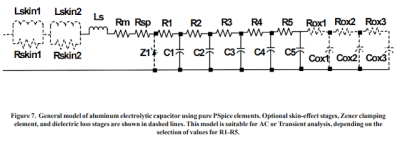
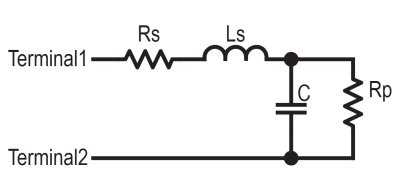
The basic equivalent circuit for a capacitor has a series resistance and inductance, which covers the connecting leads and any internal tabs on the plates. A large-valued parallel resistor models the leakage through the dielectric in series with the ideal capacitance, which is responsible for the capacitor’s self-discharge property. However, this model is still too simple for some use cases. A more interesting model, shown to the left, comprises a ladder of distributed capacitances and associated resistances that result in a progressively longer time-constant component as you move from C1 to C5. This resembles more closely the linear structure of the capacitor, with its rolled-up construction. This model is hard to use in any practical sense due to the need to determine values for the components from a physical part. Still, it is useful to understand why such capacitors perform far worse than you would expect from just a simple equivalent model that looks at the connecting leads and little else.

Continue reading “Why Is My 470uF Electrolytic Cap More Like 20uF?”

Protect Vintage Gear With Easy Capacitor Reforming

Having acquired some piece of old electronic equipment, be it a computer, radio, or some test gear, the temptation is there to plug it in as soon as you’ve lugged it into the ‘shop. Don’t be so hasty. Those power supplies and analog circuits often have a number of old aluminium electrolytic capacitors of unknown condition, and bad things can happen if they suddenly get powered back up again. After a visual inspection, to remove and replace any with obvious signs of leakage and corrosion, those remaining may still not be up to their job, with the oxide layers damaged over time when sat idle, they can exhibit lower than spec capacitance, voltage rating or even be a dead short circuit. [TechTangents] presents for us a guide to detecting and reforming these suspect capacitors to hopefully bring them, safely, back to service once more.

Capacitor failure modes are plentiful

When manufactured, the capacitors are slowly brought up to operating voltage, before final encapsulation, which allows the thin oxide layer to form on the anode contact plate, this is an electrically driven chemical process whereby a portion of the electrolyte is decomposed to provide the needed oxygen ions. When operating normally, with a DC bias applied to the plates, this oxidation process — referred to as ‘self-healing’ — continues slowly, maintaining the integrity of the oxide film, and slowly consuming the electrolyte, which will eventually run dry and be unable to sustain the insulating oxide layer.

If left to sit un-powered for too long, the anodic oxide layer will decay, resulting in reduced operating voltage. When powered up, the reforming process will restart, but this will be in an uncontrolled environment, resulting in a lot of excess heat and gases being vented. It all depends on how thin the oxide layer got and if holes have started to form. That is, if there is any electrolyte left to react – it may already be far too late to rescue.

If the oxide layer is sufficiently depleted, the capacitor will start to conduct, with a resultant self-heating and runaway thermal decomposition. They can explode violently, which is why there are score marks at the top of the can to act as a weak point, where the contents can burst through. A bit like that ‘egg’ scene in Aliens!

Yucky leaky capacitor. Replace these! and clean-up that conductive goo too.

The ‘safe’ way to reform old capacitors is to physically remove them from the equipment, and apply a low, controlled voltage below the rated value to keep the bias current at a low value, perhaps just 2 mA. Slowly, the voltage can be increased to push the current back up to the initial forming level, so long as the current doesn’t go too high, and the temperature is within sensible bounds. The process ends when the applied voltage is at the rated value and the current has dropped off to low leakage values.

A word of warning though, as the ESR of the reformed caps could be a little higher than design, which will result in higher operating temperature and potentially increased ripple current in power supply applications.

We’re really glossing over this subject fast here, but [TechTangents] was kind enough to link to some fine capacitor-related reading for those who need a primer. Here is a US DoD handbook for reforming capacitors with advice on storage shelf life, some tech notes on using electrolytic capactors from chemi-con, and a general capacitor guide from TDK. Reforming caps is nothing new, here’s an previous article about repairs, and something a bit more recent.

Continue reading “Protect Vintage Gear With Easy Capacitor Reforming”

Six Shooter Swaps Powder For Popped Capacitors

Modern firearms might seem far removed from the revolvers of the Old West, but conceptually, they still operate on the same principle: exploding gunpowder. But as anyone who has put too much voltage through an electrolytic capacitor knows, gunpowder isn’t the only thing that explodes. (Yes, it isn’t technically an explosion.)

[Jay Bowles] wondered if it would be possible to construct an electrically-fired weapon that used used a standard capacitor in place of the primer and powder of a traditional cartridge. While it would naturally have only the fraction of the muzzle velocity or energy of even the smallest caliber firearm, it would be an interesting look at an alternate approach to what has been considered a largely solved problem since the mid-1800s.

In his latest Plasma Channel video, [Jay] walks viewers through the creation of his unconventional pistol, starting with a scientific determination of how much energy you can get out of popped capacitor. His test setup involved placing a capacitor and small projectile into an acrylic tube, and noting the relation between the speed of the projectile and the voltage passed through the cap. At 30 VDC the projectile would reliably fire from the barrel of his makeshift cannon, but by tripling the voltage to 90 VDC, he noted that the muzzle velocity saw the same 3X improvement.

Continue reading “Six Shooter Swaps Powder For Popped Capacitors”

Vintage Meter Repair? It’s Easier With X-Rays

Here’s an interesting and detailed teardown and repair of a Keithley 2001 7.5 Digit multimeter that is positively dripping with detail. It’s also not every day that we get to see someone using x-ray imaging to evaluate the extent of PCB damage caused by failed electrolytic capacitors.

Dark area is evidence of damage in the multi-layer PCB.

Sadly, this particular model is especially subject to that exact vintage electronics issue: electrolytic capacitor failure and leakage. These failures can lead to destroyed traces, and this particular unit had a number of them (in addition to a few destroyed diodes, just for good measure.) That’s where the x-ray machine comes in handy, because some of the damage is hidden inside the multi-layer PCBs.

[Shahriar], perhaps best known as [The Signal Path], narrates the entire process of fixing up the high-quality benchtop multimeter in a video, embedded below (or you can skip directly to the x-ray machine being broken out.) [Shahriar] was able to repair the device, thanks in part to it being in relatively good shape, and having the right tools available. Older electronics are not always so cooperative; the older a device is, the more likely one is to run into physical and logical standards that no longer exist.

Continue reading “Vintage Meter Repair? It’s Easier With X-Rays”

Clacker Hacker: Popping A Cap In A Brother EP43 Thermal Typewriter

A few months ago, I fell down the internet rabbit hole known as Ted Munk’s typewriter site. I don’t remember if I just saw this Brother EP43 typewriter for sale and searched for information about them, or went looking for one after reading about them. Either way, the result is the same — I gained a typewriter.

Now I’m not really a typewriter collector or anything, and this is my first word processor typewriter. When it arrived from Goodwill, I anxiously popped four ‘C’ cells in and hoped for the best. It made a print head noise, so that was a good sign. But almost immediately after that, there was a BANG! and then a puff of smoke wafted out from the innards. My tiny typewriter was toast. Continue reading “Clacker Hacker: Popping A Cap In A Brother EP43 Thermal Typewriter”

Unrolling The Mystery Inside An Aluminum Electrolytic Capacitor

When we remove the enclosure of modern electronics, we see a lot of little silvery cylinders wrapped with heat shrink plastic. These aluminum electrolytic capacitors are common residents on circuit boards. We may have cut one open to satisfy our curiosity of what’s inside, but that doesn’t necessarily mean we understood everything we saw. For a more detailed guided tour, follow [TubeTime]’s informative illustrated Twitter thread.

Electronics beginners are taught the basic canonical capacitor: two metal plates and an insulator separating them. This is enough to understand the theory of capacitor operation, but there were hints the real world is not quite that simple. We don’t even need to disassemble an electrolytic capacitor to get our first hint: these cylinders have markings to indicate polarity, differentiating them from the basic capacitor which is symmetric and indifferent to polarity. Once taken apart and unrolled, we would find two thin aluminum foils separated by a sheet of paper. It would be tempting to decide the foil were our two plates and the paper is our insulator, except for the fact those two metal plates are different sizes further deviating from the basic capacitor.

Electronics veterans know the conductor–insulator–conductor pattern is not foil–paper–foil, but actually foil–oxide–electrolyte. But there is more to [TubeTime]’s tour than this answer, which includes pictures of industrial machinery, a side adventure in electrolytic chemistry using a tiny glass beaker, concluding with links to more information. And once armed with knowledge, we can better understand why electrolytic capacitors don’t necessarily need to be replaced in old equipment and appreciate them within the larger history of capacitors context.

Top Off A Dry Electrolytic

Making a capacitor is pretty easy. Just get two conductors close together. The bigger area you can get and the closer you can get them, the bigger the capacitor you can make. [BigClive] found some fake capacitors that were supposed to be very high value, but weren’t. Taking them apart revealed the capacitors didn’t have the electrolyte inside that gives these units both their name and their high values. What did he do? Mixed up some electrolyte and filled them back up to see what would happen. You can see the video below.

Electrolytic capacitors have a secret weapon to get the two electrodes as close as possible to each other. The electrolyte forms a very thin insulating layer on one electrode and the capacitance is between the conductive fluid and that electrode — not between the two electrodes. This allows for a very narrow gap between the conductors and explains why a small electrolytic can have a much greater capacitance than most other technologies in similar form factors.

Continue reading “Top Off A Dry Electrolytic”