STM32 Offers Performance Gains For DIY Oscilloscope

There’s no shortage of cheap digital oscilloscopes available today from the usual online retailers, but that doesn’t mean the appeal of building your own has gone away — especially when we have access to powerful microcontrollers that make it easier than ever to spin up custom gear. [mircemk] is using one of those microcontrollers to build an improved, pocket-sized oscilloscope.

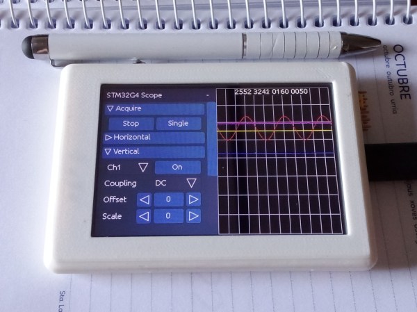
The microcontroller he’s chosen is the STM32F103C8T6, part of the 32-bit STM family which has tremendous performance compared to common 8-bit microcontrollers for only a marginally increased cost. Paired with a small 3-inch TFT color display, it has enough functions to cover plenty of use cases, capable of measuring both AC and DC signals, freezing a signal for analysis, and operating at an impressive 500 kHz at a cost of only around $15. The display also outputs a fairly comprehensive analysis of the incoming signal as well, with the small scope capable of measuring up to 6.6 V on its input.

This isn’t [mircemk]’s first oscilloscope, either. His previous versions have used Arduinos, generally only running around 50 kHz. With the STM32 microcontroller the sampling frequency is an order of magnitude higher at 500 kHz. While that’s not going to beat the latest four-channel scope from Tektronix or Rigol, it’s not bad for the form factor and cost and would be an effective scope in plenty of applications. If all you have on hand is an 8-bit microcontroller, though, we have seen some interesting scopes built with them in the past.

Simple STM32 Frequency Meter Handles Up To 30MHz With Ease

[mircemk] had previously built a frequency counter using an Arduino, with a useful range up to 6 MHz. Now, they’ve implemented a new design on a far more powerful STM32 chip that boosts the measurement range up to a full 30 MHz. That makes it a perfect tool for working with radios in the HF range.

The project is relatively simple to construct, with an STM32F103C6 or C8 development board used as the brains of the operation. It’s paired with old-school LED 7-segment displays for showing the measured frequency. Just one capacitor is used as input circuitry for the microcontroller, which can accept signals from 0.5 to 3V in amplitude. [mircemk] notes that the circuit would be more versatile with a more advanced input circuit to allow it to work with a wider range of signals.

It’s probably not the most accurate frequency counter out there, and you’d probably want to calibrate it using a known-good frequency source once you’ve built it. Regardless, it’s a cheap way to get one on your desk, and a great way to learn about measuring and working with time-varying signals. You might like to take a look at the earlier build from [mircemk] for further inspiration. Video after the break.

Continue reading “Simple STM32 Frequency Meter Handles Up To 30MHz With Ease”

Hackaday Prize 2023: 10 KW Electronic Load

[tinfever] needed a high-power benchtop electronic load for an upcoming project, and by their own admission decided foolishly to build their own. And we’re glad they did. The thing is, whilst this isn’t exactly a super-cheap project to build, buying a commercial offering with a capability of 10 kW and up to 30 kW pulsed, is going to cost an absolute fortune.

A selection of small resistors

Built inside a cubic frame using what appears to be standard 2020 aluminum rails and fixturing, the modular construction is nice and clean, with plenty of space around the load boards to allow the cooling air to circulate.

The operating principle is very simple; custom PCBs act in parallel to provide any load needed, by switching in the on-board load resistor. Each load board handles all the details of switching and dumping the power due to the inductance in the system wiring and the wire-wound resistors themselves.

Whilst we know that wire-wound resistors are reverse-wound to minimize inductance, there will still be some, and each load board will contribute a little more when the whole system is scaled up. Also, each load PCB handles its own temperature sensing, and current measurement passing these data off to the control PCB. A front-end connector PCB provides a variety of connection options to interface to the DUT (Device Under Test.) The system controller is based around an STM32 processor which deals with quite a lot more than you might think is needed on a first look.

The sense currents from each load need to be sensed, scaled, and summed to keep the overall load accuracy within the 1% spec. Also, it is on duty for PWM control of the cooling fans, handling the user interface, and any other remote connectivity. There are a lot of details on the project page, as we’re only skimming the surface here. If you’re interested in building an active load, this is a project you really should be digging into.

We shall watch with interest for when [tinfever] scales up this eight-slot prototype to the full specification of 52 stages! When working with power applications, there comes a point when you really need an electronic load, and to that end, here’s one with a very specific use case to get you started.

There is also the option of buying something cheap from the usual sources and hacking on some custom firmware to adapt it a little to your needs.


Hackaday Prize 2023: Over-the-Top Programmable Resistor Looks The Part And Performs

Every once in a while we get wind of a project that we’re reluctant to write up for the simple reason that it looks too good to be true. Not that projects need to be messy to be authentic, mind you, but there are some that are just so finished and professional looking that it gives us a bit of pause. [Sebastian]’s programmable precision resistor is a shining example of such a project

While [Sebastian] describes this as “a glorified decade resistance box,” and technically that’s exactly right — at its heart it’s just a bunch of precision resistors being switched into networks to achieve a specific overall resistance — there’s a lot more going on here than just that. The project write-up, which has been rolling out slowly over the last month or so, has a lot of detail on different topologies that could have been used — [Sebastian] settled on a switched series network that only requires six relays per decade while also minimizing the contribution of relay contact resistance to the network. Speaking of which, there’s a detailed discussion on that subject, plus temperature compensation, power ratings, and how the various decades are linked together.

For as much that’s interesting about what’s under the hood, we’d be remiss to not spend a little time praising the exterior of this instrument. [Sebastian] appears to have spared no expense to make this look like a commercial product, from the rack-mount enclosure to the HP-esque front panel. The UI is all discrete pushbuttons and knobs with a long string of 16-segment LEDs — no fancy touch-screens here. The panel layout isn’t overly busy, and looks like it would be easy to use with some practice. We’d love to hear how the front and rear panel overlays were designed, too; maybe in a future project update.

This honestly looks like an instrument that you’d pay a princely sum to Keithley or H-P to own, at least back in the late 1990s or so. Kudos to [Sebastian] for the attention to detail here.

STM32 Oscilloscope Uses All The Features

[jgpeiro] is no slouch when it comes to building small, affordable oscilloscopes out of common microcontrollers. His most recent, based on an RP2040 with two channels that ran at 100 MSps, put it on the order of plenty of commercially-available oscilloscopes at this sample rate but at a fraction of the price. He wanted to improve on the design though, making a smaller unit with a greatly reduced bill-of-materials and with a more streamlined design, so he came up with this STM32-based oscilloscope.

The goal of this project was to base as many of the functions around the built-in capabilities of the STM32 as possible, so in addition to the four input channels and two output channels running at 1 MHz, the microcontroller also drives a TFT display which has been limited to 20 frames per second to save processor power for other tasks. The microcontroller also has a number of built-in operational amplifiers which are used as programmable gain amplifiers, further reducing the amount of support circuitry needed on the PCB while at the same time greatly improving the scope’s capabilities.

In fact, the only parts of consequence outside of the STM32, the power supply, and the screen are the inclusion of two operational amplifiers included to protect the input channels from overvoltage events. It’s an impressive build in a small form factor, and we’d say the design goal of keeping the parts count low has been met as well. If you do need something a little faster though, his RP2040-based oscilloscope is definitely worth checking out.

Continue reading “STM32 Oscilloscope Uses All The Features”

Blinkenlights To Bootloader: A Guide To STM32 Development

While things like the Arduino platform certainly opened up the gates of microcontroller programming to a much wider audience, it can also be limiting in some ways. The Arduino IDE, for example, abstracts away plenty of the underlying machinations of the hardware, and the vast amount of libraries can contribute to this effect as well. It’s not a problem if you just need a project to get up and running, in fact, that’s one of its greatest strengths. But for understanding the underlying hardware we’d recommend taking a look at something like this video series on the STM32 platform.

The series comes to us from [Francis Stokes] of Low Byte Productions who has produced eighteen videos for working with the STM32 Cortex-M4 microcontroller. The videos start by getting a developer environment up and blinking LEDs, and then move on to using peripherals for more complex tasks. The project then moves on to more advanced topics and divides into two parts, the development of an application and also a bootloader. The bootloader begins relatively simply, and then goes on to get more and more features built into it. It eventually can validate and update firmware, and includes cryptographic signing (although [Francis] notes that you probably shouldn’t use this feature for production).

One of the primary goals for [Francis], apart from the actual coding and development, was to liven up a subject matter that is often seen as dry, which we think was accomplished quite well. A number of future videos are planned as well. But, if you’re not convinced that the STM32 platform is the correct choice for you, we did publish a feature a while back outlining a few other choices that might provide some other options to consider.

Continue reading “Blinkenlights To Bootloader: A Guide To STM32 Development”

Networking With Balloons

Starlink has been making tremendous progress towards providing world-wide access to broadband Internet access, but there are a number of downsides to satellite-based internet such as the cluttering of low-Earth orbit, high expense, and moodiness of CEO. There are some alternatives if standard Internet access isn’t available, and one of the more ambitious is providing Internet access by balloon. Project Loon is perhaps the most famous of these (although now defunct), but it’s also possible to skip the middleman and build your own high-altitude balloon capable of connection speeds of 500 Kbps.

[Stephen] has been working on this project for a few months and while it doesn’t support a full Internet connection, the downlink on the high altitude balloon is fast enough to send high-resolution images in near-real-time. This is thanks to a Raspberry Pi Zero on board the balloon that is paired with an STM32 board which handles the radio communication on a RF4463 transceiver module. The STM32 acts as an intermediary or buffer to ensure reliable information is sent out on the radio, rather than using the Pi directly. [Stephen] also wrote a large chunk of the software responsible for handling all of these interactions, optimized for balloon flight specifically.

The blog post for this project was written a few weeks ago with a reported first launch date for the system already passed, so we will eagerly anticipate the results and the images he was able to gather using this system. Eventually [Stephen] hopes the downlink will be fast enough for video as well.Balloons are an underappreciated tool as well, and this isn’t the only way that they can be used to help send radio signals from place to place.