Very Accurate Clock Can’t Be Read Accurately

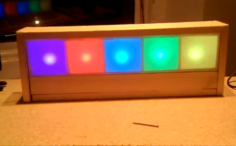
[Martijn] is showing off his new clock which he calls a Light Spectrum Clock. We like to look of it, using RGB LEDs in five squares that remind us of some of those LED coffee table builds. From left to right this shows the week, day, hour, minute, and second. Simple, right?

We had to smile a little bit when looking through his write up. He chose an Arduino nano as a controller, using a TLC5940 chip to drive the LEDs. But it is the inclusion of a DS1307 real-time clock that we find amusing. It will keep quite accurate time (not quite as well as the DS3232 but still respectable) but the fuzzy display technique makes telling the time accurately an impossibility. But like other color-based clocks, that’s part of the fun. The real reason for using an RTC chip is that they usually include battery-backed operation so that you can shut off the LEDs when you’re not around and the clock will continue to tick.

You can watch the seconds pass by as fading colors in the clip after the break.

Continue reading “Very Accurate Clock Can’t Be Read Accurately”

Modular Controllers You Can’t Wait To Show Off To Your Friends

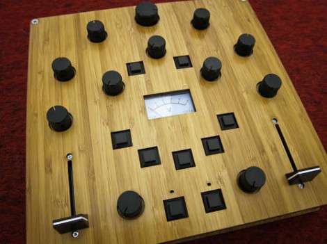
Let’s get this straight, [Alex] is going to show us how to make controllers like this one? Where do we sign up? Even without seeing it in action we want one, but the urge to build is even greater after he shows it off (check the clip after the break). He’s a design student who made an open source project aimed at making it easier to build hardware controllers that pair with just about any software application.

The need for external controllers is on the rise, starting with music-based applications like DJ tools, and Midi controllers for musicians (we’re thinking Monome clones). But anything that can take input from a USB HID can be controlled with something like this. That’s because [Alex] is using the Teensy controller board as an interface. Just select the input types you want – sliders, potentiometers, buttons, switches – then wire them up to the microcontroller pins. If you start to run out of inputs he also discusses some add-on chips to use as port expanders.

Of course there’s a lot to be said for the physical appearance as well. Even though he used point-to-point connections for all of the controls, that wiring is hidden behind the aesthetically pleasing laser-cut dashboard. Follow his advice for layout and find a friend with access to a sweet laser cutter and you’re in business. Continue reading “Modular Controllers You Can’t Wait To Show Off To Your Friends”

Tutorial: Build A Manifold Clock For $10

Every once in a while, the Hack a Day tip line gets a submission that is cool, but screams to be built in a few hours, possibly while consuming adult beverages. When [Shay] and [Ben] sent in their Manifold Clock Kickstarter, I knew what I had to do. To make a long story short, there’s a manifold clock hanging on my wall right now. Check out my manifold clock how-to guide after the break.

Continue reading “Tutorial: Build A Manifold Clock For $10”

Control Android With A Projector And Kinect

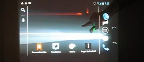
If you’re going to build a giant touch screen, why not use an OS that is designed for touch interfaces, like Android? [Colin] had the same idea, so he connected his phone to a projector and a Kinect.

Video is carried from [Colin]’s Galaxy Nexus to the projector via an MHL connection. Getting the Kinect to work was a little more challenging, though. The Kinect is connected to a PC running Simple Kinect Touch. The PC converts the data from the Kinect into TUIO commands that are received using TUIO for Android.

In order for the TUIO commands to be recognized as user input, [Colin] had to compile his own version of Android. It was a lot of work, but using an OS designed for touch interface seems much better than all the other touch screen hacks that start from the ground up.

You can check out [Colin]’s demo after the break. Sadly, there are no Angry Birds.

Continue reading “Control Android With A Projector And Kinect”

Challenge: Figure Out How This Logic-based Chaser Works

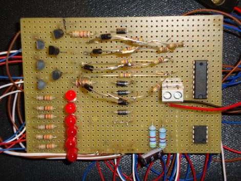
[Andrea] built this LED chaser using one logic chip. It illuminates all but one of the six LEDs, with the dim bit moving back and forth along the row in a chase sequence. This is something like an inverse Larson Scanner without the fading tail. But doing it with a logic chip instead of a microcontroller is a fun challenge.

Which brings us to the point of this feature. [Andrea] didn’t really post an explanation of how the circuit works. Usually missing details mean that we archive the tip and move on to the next one, but we think this provides a fun activity. Can you figure out how the circuit works? We already know that it’s using a CD4017 decade counter/divider chip. This gets its clock signal from a 555 timer circuit. [Andrea’s] schematic is a bit hard to read, but grab a copy, blow it up a bit (or use your browser zoom) and study the CD4017 datasheet (PDF) if you need to.

Want proof that it does actually work? It’s embedded after the break.

Continue reading “Challenge: Figure Out How This Logic-based Chaser Works”

Custom Microcontroller Using Only A Dremel

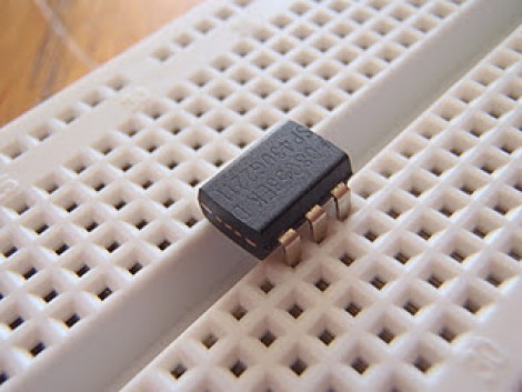
Check out this 6-pin MSP430 microcontroller. What’s that you say? TI doesn’t make a 6-pin MSP430? True, Texas Instruments doesn’t make one, so [Greg] grabbed his Demel and a cutoff wheel, and chopped up a larger uC to arrive at this package.

It may sound a bit crazy at first, but when you think about it there’s nothing really all that special about this. The plastic package on DIP components these days is mostly empty. The silicon die which does the computing is quite small in comparison, and usually mounted in the very center of the part. [Greg] simply cut off eight of the unneeded pins (four from each end).

Well, it might be a stretch to call them unneeded since he cut the ground and voltage pins. He gets around this issue by taking advantage of the same properties of the I/O pins used in this barebones RFID tag. You can inject power through the I/O and we’d bet you could easily use this chopped-up MSP430G2211 as an RFID tag if you wanted to.

[Thanks Ian]

Bending A Printer Control Board To Output POV Messages

Confronted with the issue of finding a use for his mounting pile of junk electronics, [Rue] set out to build a persistence of vision device using a hardware state machine. We have a suspicion that his original link may go down if there’s too much traffic so here’s a cached link just in case.

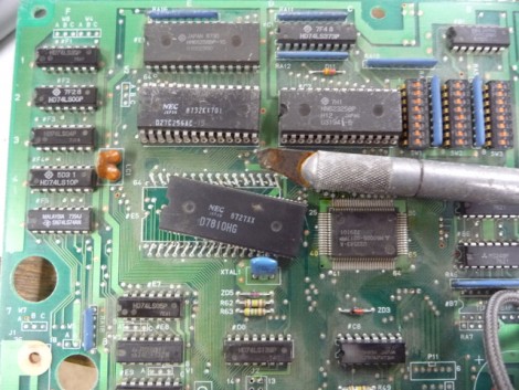
Any board that is MSC-51 or MCS-48 based would have worked for his purposes. This is because the addressing scheme of the hardware makes it an easy hack. The image above shows him cutting off the processor from this board. It was chosen because of a 74HC373; it was a mistake at first but since it’s pin compatible with the 74HC374 that he needed a simple swap did the trick. From there a clock source was added, and the address information necessary to display the message was burned into an EEPROM.

Step twelve of his writeup shows a Morse Code message created by attaching the board to a broomstick and twirling it around in an arc. We took  just a minute to decode the message and believe it’s a shout-out to Hackaday. Nice, thanks for reading [Rue]!