Measuring The Lifespan Of Nixie Tubes

nixie

Nixie tubes have two things going for them: they’re awesome, and they’re out of production. If you’re building a clock – by far the most popular Nixie application, you’re probably wondering what the lifespan of these tubes are. Datasheets from the manufacturers sometimes claim a lifetime as low as 1000 hours, or a month and a half if you’re using a tube for a clock. Obviously some experimentation is in order to determine the true lifetime of these tubes.

Finding an empirical value for the lifetime of Nixies means setting up an experiment and waiting a very, very long time. Luckily, the folks over at SALTechips already have a year’s worth of data.

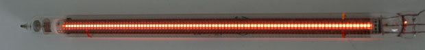
Their experimental setup consists of an IN-13 bargraph display driven with a constant current sink. The light given off by this Nixie goes to a precision photometer to log the visual output. Logging takes place once a week, and the experiment has been running for 57 weeks so far.

All the data from this experiment is available on the project page, along with a video stream of the time elapsed and current voltage. So far, there’s nothing to report yet, but we suppose that’s a good thing.

An ARM Powered Business Card, Part Two

Card

While most microcontroller powered business cards opt for something small and cheap, [Brian] is going in an entirely different direction. His business card features an ARM processor, some Flash storage, a USB connection, and enough peripherals to do some really cool stuff.

This is the second iteration of [Brian]’s business card. We saw the first version, but this new version makes up for a few mistakes in the previous version. The biggest improvement is the replacement of the Molex USB plug with bare traces on the board. [Brian] couldn’t find a board house that could fab a board with the proper thickness for a USB plug, but a few strips of masking tape did enough to beef up the thickness and make his plug nice and snug. Also, the earlier version had a few pins sticking out of the board for programming purposes. This wasn’t an idea solution for a business card where it would be carried around in a pocket, so these pins were replaced with a connectorless programming adapter. Just a few exposed pads gives [Brian] all the programming abilities of the last version, without all those prickly pins to catch on clothing.

With his new business card, [Brian] has an excellent display of his engineering prowess and a very cool toy; he has a project that will turn this card into a keyboard emulator, randomly activating the Caps Lock button for a few seconds every few minutes. A great prank, and a great board to give to future employers.

Pimp My Keyboard: Automatic Lift Kit And More

Cherry-keyboard-with-lifts

Wondering what the heck a lift kit is? You know those low-riding cars that bounce? That’s the idea with this hack. [Justblair] added automatic height adjustment to his Cherry G80, and hid a few other extras while he was at it. Since there’s a fair amount of room inside the case of this model he was able to hide everything and keep just a single cord to run it all.

Certainly what catches your eye is the keyboard’s ability to rise to a typing height automatically. This is accomplished with a few servo motors and some 3D printed replacement feet. There were some hiccups along the way with under-powered servos, but bulking up to some HXT 900 9G models provide more power than is currently necessary. The automatic feature is thanks to a capacitive sensor built with a wire that loops the perimeter of the keyboard.

Of course to monitor the sensor and drive the servos you need some kind of brain. For that [Justblair] went with an ATmega32U4 breakout board. Since he had to patch into USB for power anyway he added a USB hub and routed one of the ports out the left side of the keyboard as a convenient way to connect other peripherals. There was even room to include an RFID reader which he uses to unlock his sessions (similar to the desk install from earlier this year). There’s still a lot of potential left in that hardware. To make future improvements easier the hack includes an IDC socket as an auxiliary port.

[Justblair] did a great job of sharing his work. His post links to a Github repo for the code and a Thingiverse project for the 3D printed legs. And it wouldn’t be complete without the demo video which is found below.

Continue reading “Pimp My Keyboard: Automatic Lift Kit And More”

Building An LED Source For A Fiber Optic Ring Light

[Peter] has finished up his fiber optic microscope light source. When we last visited [Peter] he created a dimmer circuit for a 10 watt LED. That LED driver has now found its final home in [Peter’s] “Franken-ebay scope”, a stereo microscope built from parts he acquired over several years. Stereo microscopes scopes like these are invaluable for working on surface mount parts, or inspecting PCB problems. [Peter] had the fiber optic ring and whip, but no light source. The original source would have been a 150W Halogen lamp. The 10 watt led and driver circuit was a great replacement, but he needed way to interface the LED to the fiber whip. Keeping the entire system cool would be a good idea too.

This was no problem for [Peter], as he has access to a milling machine. He used an old CPU heat sink from his junk box as the base of the light source. The heat sink was drilled and tapped for the LED. The next problem was the actual fiber whip interface. For this, [Peter] milled a custom block from aluminum bar stock. The finished assembly holds the LED, driver, and the fiber whip. A sheet metal bracket allows the entire assembly to be mounted on the microscope’s post.  We have to admit, if we were in [Peter’s] place, we would have gone with a cheap LED ring light. However, the end result is a very clean setup that throws a ton of light onto whatever [Peter] needs magnified.

Continue reading “Building An LED Source For A Fiber Optic Ring Light”

ATMega16 Hard Disk Clock

Hard-Disk-Clock-by-Martin-Stromer_3338278

[Martin Stromer] made this great looking Hard Disk Clock about 12 years ago, and finally decided to share it with the world. It’s been “ticking” ever since.

It’s a beautiful clock, and if you think the drive might look a bit odd, that’s probably because its well over 20 years old! We’re not too sure the capacity, but it couldn’t have been more than a few dozen megabytes.

To read the time, the platter rotates 30 degrees at once, per hour. The read-write head inches across the disc to display the minutes. Each of the black lines represents a quarter hour. The whole thing is controlled by an ATMega16, which maintains almost all of the original hardware. The blog post has a great write-up on how it all works.

Did we mention it’s also easy to set the time? Simply rotate the disc by hand and slide the read-write head into place, then press the reset button. Check out the clock in action after the break.

Continue reading “ATMega16 Hard Disk Clock”

Wireless MIDI Floor Piano!

123

[Jianan Li] just finished documenting one of his most recent projects, a wireless MIDI floor piano that he and a small group made for Duke University’s Hackathon!

He was inspired to do this project after reading our recent coverage on a DIY Pressure Plate. Having only 24 hours to compete in the Hackathon, they had to choose something that was fairly easy to build out of cheap materials, and quick to assemble. This was just the ticket.

The piano features 25 of the aluminum foil pressure plates, whose state are read by the Arduino Mega. This is then transmitted by an XBee radio to an Arduino Uno, which acts as the receiver for the laptop that processes the signals. They even added a remote control using an ATtiny85 to allow for octave and instrument changes — it also uses an XBee to communicate back to the Uno. For a 24 hour build, the quality is quite impressive, and it doesn’t sound half bad either — Take a listen after the break!

Continue reading “Wireless MIDI Floor Piano!”