Hackaday Links Column Banner

Hackaday Links: March 22, 2015

[Liam Kennedy] built a wearable space station notifier it’s on Kickstarter, and now the campaign is in its final hours. It’s very cool; doubly so if you don’t have to talk to a crazy lady who doubts the existence of NASA.

[countkillalot] lost a Raspberry Pi. It was in his apartment, and responded to ping, but he couldn’t find it. Turning the Pi into an FM transmitter revealed its location. Relevant bash.org.

If you don’t listen to the Amp Hour podcast, oh man are you in for a treat. This time it’s [Chuck Peddle], father of the 6502, designer of the KIM-1, and someone with at least three hours’ worth of interesting stories.

MakeIt Labs, the Nashua, New Hampshire hackerspace, has done everything right – they have their 501(c)(3), and they’ve been talking to the city about getting a new space. They have the option of moving into a space three times the size as their current one, and it’s cheaper than the current space. They have an indiegogo to raise the renovation funds for the new space. Oh, hackaday.io supports pages for hackerspaces. Just pointing that out.

Speaking of hackerspaces, yours needs this sign.

A 3-DAY DESERT CAMPING AND TECH-FEST WITH BEER. That’s all you need to know about Arduino Day, an event being held next weekend in the Mojave.

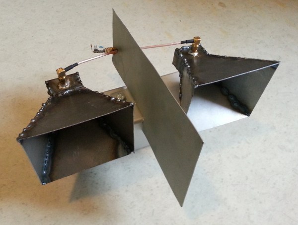
Want to hide from the NSA, or whatever governments or corporate interests are listening in on your phone? Stick it in a microwave. [WhiskeyTangoHotel] tested out a Tek RSA306 spectrum analyzer in a microwave, once with the door open, once with the door closed. If you’re exceptionally clever or have access to Wikipedia, you can figure out what frequencies will leak out of a microwave given the size of the holes in the metal mesh.

Here’s a Flintstones toilet paper holder. It would have been a phonograph, but no one could find a cooperative turtle and bird.

It has been brought to our attention that everyone should be aware ucapps.de still exists. If you want something that does everything with MIDI and SID chips, there you go.

BeagleBones At MRRF

[Jason Kridner] – the BeagleBone guy – headed out to the Midwest RepRap Festival this weekend. There are a lot of single board computers out there, but the BeagleBoard and Bone are perfectly suited for controlling printers, and motion control systems thanks to the real-time PRUs on board. It’s not the board for you if you want to play retro video games or build a media center; it’s the board for building stuff.

Of interest at the BeagleBooth were a few capes specifically designed for CNC and 3D printing work. There was the CRAMPS, a clone of the very popular RAMPS 3D printer electronics board made for the Beagle. If you’re trying to control an old mill that is only controllable through a parallel port, here’s the board for you. There are 3D printer boards with absurd layouts that work well as both printer controller boards and the reason why you should never come up with the name of something before you build it.

[Jason]’s trip out to MRRF wasn’t only about extolling the virtues of PRUs; Machinekit, a great motion control software, was also there, running on a few Beagles. The printer at the BeagleBooth was running Machinekit and apart from a few lines of GCode that sent the head crashing into the part, everything was working great.

Continue reading “BeagleBones At MRRF”

Horn Antenna

Building A Horn Antenna For Radar

So you’ve built yourself an awesome radar system but it’s not performing as well as you had hoped. You assume this may have something to do with the tin cans you are using for antennas. The obvious next step is to design and build a horn antenna spec’d to work for your radar system. [Henrik] did exactly this as a way to improve upon his frequency modulated continuous wave radar system.

To start out, [Henrik] designed the antenna using CST software, an electromagnetic simulation program intended for this type of work. His final design consists of a horn shape with a 100mm x 85mm aperture and a length of 90mm. The software simulation showed an expected gain of 14.4dB and a beam width of 35 degrees. His old cantennas only had about 6dB with a width of around 100 degrees.

The two-dimensional components of the antenna were all cut from sheet metal. These pieces were then welded together. [Henrik] admits that his precision may be off by as much as 2mm in some cases, which will affect the performance of the antenna. A sheet of metal was also placed between the two horns in order to reduce coupling between the antennas.

[Henrik] tested his new antenna in a local football field. He found that his real life antenna did not perform quite as well as the simulation. He was able to achieve about 10dB gain with a field width of 44 degrees. It’s still a vast improvement over the cantenna design.

If you haven’t given Radar a whirl yet, check out [Greg Charvat’s] words of encouragement and then dive right in!

RaspPi2 Keyboard

RaspPi/Keyboard Project Called Kiiboard, Still Pronounced ‘keyboard’

[b10nik] wrote in to tell us about a pretty sweet project that he just finished up. It’s a mechanical keyboard with an integrated Raspberry Pi 2 Model B inside.

[b10nik] purchased a new Filco Ninja Majestouch-2 keyboard just for this project. Although it may make some people cringe, the keyboard was immediately taken apart in order to find an open cavity for the Raspberry Pi. Luckily there was space available towards the left rear of the keyboard case.

RaspPi2 Keyboard inside
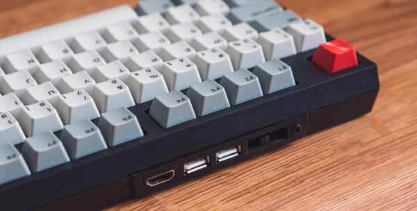
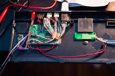
If you are familiar with the Raspberry Pi 2 Model B, you know that all of the connections are not on the same side of the board. The USB, audio, HDMI and Ethernet jacks were removed from the PCB. The Ethernet port is not needed since this hack uses WiFi, but those those other ports were extended and terminated in a custom 3D printed I/O panel . The stock keyboard case had to be cut to fit the new panel which results in a very clean finished look.

There’s one more trick up this keyboard’s sleeve, it can be used with the internal Raspberry Pi or be used as a standard keyboard. This is done by way of a FSUSB30MUX USB switch IC that completely disconnects the Raspberry Pi from the keyboard’s USB output.

For another RaspPi/Keyboard solution, check out this concept from a few years ago using a Cherry G80-3000 mechanical keyboard.


Swapping Dev Board Crystals To Suit Your Needs

Microcontroller Dev Boards have the main hardware choices already made for you so you can jump right into the prototyping by adding peripherals and writing code. Some of the time they have everything you need, other times you can find your own workarounds, but did you ever try just swapping out components to suit? [Andy Brown] documented his process of transplanting the clock crystal on an STM32F4 Discovery board.

Even if you don’t need to do this for yourself, the rework process he documented in the clip after the break is fun to watch. He starts by cleaning the through-hole joints of the crystal oscillator with isopropyl alcohol and then applies some flux paste to each. From there the rest is all hot air. The crystal nearly falls out due to gravity but at the end he needs to pluck it out with his fingers. We’re happy to see others using this “method” as we always feel like it’s a kludge when we do it. Next he grabs the load caps with a pair of tweezers after the briefest of time under the heat.

We’d like to have a little bit of insight on the parts he replaces and we’re hoping there are a few crystal oscillator experts who can leave a comment below. [Andy] calculates a pair of 30pf load caps for this crystal. We understand the math but he mentions a common value for board and uC input capacitance:

assuming the commonly quoted CP + CI = 6pF

So we asked and [Andy] was kind enough to share his background on the topic:

It’s a general “rule of thumb” for FR4 that the stray capacitance due to the traces on the board and the input (lead) capacitance of the the MCU is in in the range of 4-8pF. I’m used to quoting the two separately (CP,CI) but if you look around you’ll see that most people will combine the two and call it just “CP” and quote a value somewhere between 4 and 8pF. It’s all very “finger in the air” and for general purpose MCU clocks you can get away picking the mid-value and be done with it.

That leaves just one other question; the original discovery board had an in-line resistor on one of the crystal traces which he replaces with a zero ohm jumper. Is it common to include a resistor and what is the purpose for it?

Continue reading “Swapping Dev Board Crystals To Suit Your Needs”

DIY Bearing Puller

DIY Car Wheel Bearing Puller

Cars are the greatest. They get you to where you need to go… most of the time. They can also let you down at the worst moment if a critical part fails.  Wheel bearings get a lot of use while we drive and [Dmitriy] found out the hard way how quickly they can fail. Instead of getting cranky about it, he set out to change the damaged bearing himself. In the process he made a pretty neat DIY bearing puller.

Some wheel bearings, on the front of a 2WD truck for example, are only held on by one large nut and easily slide off the spindle. This was not the case for the rear of [Dmitriy’s] AWD Subaru. The rear bearings are press-fit into a bearing housing. These are hard to remove because Outer Diameter of the bearing is actually just slightly larger than the Inner Diameter of the bearing housing. This method of retaining parts together is called an ‘interference fit‘.

BearingPuller2

[Dmitriy’s] gadget uses one of Hackaday’s favorite simple machines, the screw, to slowly force the bearing out of its housing. It works by inserting a threaded rod through the bearing and bearing housing. Each side has a large washer and nut installed as well as a PVC pipe spacer providing support for the threaded rod. As the opposing nuts are tightened, one washer presses against the bearing and the bearing slowly slides out of the housing. Installation of the new bearing is the same except the tool is reversed to press the bushing into the housing.

Continue reading “DIY Car Wheel Bearing Puller”

Your Marble Machine Doesn’t Need To Change The World

It’s easy to get sucked into the increasing the complexity when sometimes the craftsmanship can be what makes the project. [Alex Weber] proves the point with his minimalist marble machine. There are no death-defying twists and turns, no convoluted path forks or overly-complex lifting mechanisms. This is about a clean and simple design that looks amazing whether running or stationary.

For the uninitiated, marble machines route marbles (or quite often steel ball bearings) through a set of paths usually guided by gravity for the delight of onlookers. Traditionally, making them complicated is the point. Take this offering which highlights years worth of marble machine builds all exercising different concepts. Sometimes they occupy entire rooms. We’ve seen them make a clock tick. And who can forget marble-based flip-flops that combine to form things like binary adders?

Have we scared you off from building these yourself yet? No, that’s the entire point of this one… it can be excruciatingly simple, while elegantly crafted. Check out the video demo below to see how one oval, one battery, and one motor have no problem bringing a smile to your face.

Continue reading “Your Marble Machine Doesn’t Need To Change The World”