A Stylish Pair Of FPGA Earrings

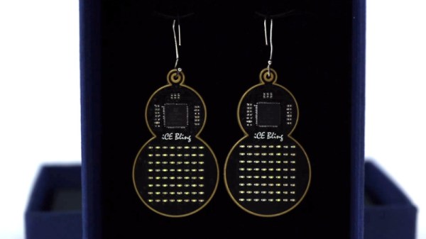
Sometimes, rather than going the commercialistic route, it can be nice to make a gift for that personal touch. [Mahesh Venkitachalam] had been down this very road before, often stumbling over that common hurdle of getting in too deep and missing the deadline of the occasion entirely. Not eager to repeat the mistake, help was enlisted early, and the iCE bling earrings were born.

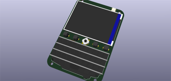
The earrings were a gift for [Mahesh]’s wife, and were made in collaboration with friends who helped out with the design. The earrings use a Lattice iCE40UP5k FPGA to control an 8×8 grid of SMD LEDs. This is all achieved without the use of shift registers, with the LEDs all being driven directly from GPIO pins. This led to several challenges, such as routing all the connections and delivering enough current to the LEDs. The final PCB is a 4-layer design, which made it much easier to get all the lines routed effectively. A buffer is used to avoid damaging the FPGA by running too many LEDs at once.

It’s a tidy build, which makes smart choices about component placement and PCB design to produce an attractive end result. LEDs naturally lend themselves to jewelry applications, and we’ve seen some great designs over the years. Video after the break.

Continue reading “A Stylish Pair Of FPGA Earrings”

3D Printering: The Past And Future Of Prusa’s Slicer

If you own a desktop 3D printer, you’re almost certainly familiar with Slic3r. Even if the name doesn’t ring a bell, there’s an excellent chance that a program you’ve used to convert STLs into the G-code your printer can understand was using Slic3r behind the scenes in some capacity. While there have been the occasional challengers, Slic3r has remained one of the most widely used open source slicers for the better part of a decade. While some might argue that proprietary slicers have pulled ahead in some respects, it’s hard to beat free.

So when Josef Prusa announced his team’s fork of Slic3r back in 2016, it wasn’t exactly a shock. The company wanted to offer a slicer optimized for their line of 3D printers, and being big proponents of open source, it made sense they would lean heavily on what was already available in the community. The result was the aptly named “Slic3r Prusa Edition”, or as it came to be known, Slic3r PE.

Ostensibly the fork enabled Prusa to fine tune print parameters for their particular machines and implement support for products such as their Multi-Material Upgrade, but it didn’t take long for Prusa’s developers to start fixing and improving core Slic3r functionality. As both projects were released under the GNU Affero General Public License v3.0, any and all of these improvements could be backported to the original Slic3r; but doing so would take considerable time and effort, something that’s always in short supply with community developed projects.

Since Slic3r PE still produced standard G-code that any 3D printer could use, soon people started using it with their non-Prusa printers simply because it had more features. But this served only to further blur the line between the two projects, especially for new users. When issues arose, it could be hard to determine who should take responsibility for it. All the while, the gap between the two projects continued to widen.

With a new release on the horizon that promised to bring massive changes to Slic3r PE, Josef Prusa decided things had reached a tipping point. In a recent blog post, he announced that as of version 2.0, their slicer would henceforth be known as PrusaSlicer. Let’s take a look at this new slicer, and find out what it took to finally separate these two projects.

Continue reading “3D Printering: The Past And Future Of Prusa’s Slicer”

Feather Plus Blackberry Equals Open Source Fauxberry

The keyboard is a superior means of input, but to date no one has really figured out how to make a keyboard for small, handheld electronics. You could use tact switches, but that’s annoying, or you could use a touch screen. The best option we’ve seen is actually a Blackberry keyboard, and [arturo182] has the best example yet. It’s a small handheld device with a screen, keyboard, and WiFi that’s ready to do anything imaginable. Think of it as an Open Source Fauxberry. In any case, we want it.

This project is actually a breakout board of sorts for the Adafruit Feather system, and therefore has support for WiFi, cellular, or pretty much any other networking of connectivity. To this blank canvas, [arturo] added an accelerator/magnetometer sensor, a single Neopixel, and of course the beautiful Blackberry keyboard. This keyboard is attached to an ATSAMD20G, a microcontroller with a whole bunch of I/O that translates key presses into I2C for the Feather.

Aside from that, there’s also a gigantic screen to display just about anything you would want in a portable computing device. There’s still a bit more work to do on this project, most notable figuring out where the battery goes, but [arturo] is developing everything in a livestream, someting we love to see as it really puts a focus on how much effort goes into making custom hardware.

Better Simulators With Homemade Potentiometers

Perhaps you’ve played a flight simulator before, using something like a mouse and keyboard. That’s a fine experience, but like any other activity you can get a lot more out of it if you put a little more effort into the experience. Some will upgrade to a joystick for a modest improvement, and others will build incredible accurate cockpit replicas down to the smallest detail. The builders of these “pits” are always looking for ways of improving their setups, and it’s from this world that we find a method of building specialized, inexpensive hall-effect sensors.

A hall-effect sensor is a circuit that outputs a voltage based on the presence of an external magnetic field. These can be used to make compasses, but with a permanent magnet in close proximity can also be used to create a potentiometer-like device at lower cost and with higher precision than a similarly-priced pot. There was a method of building these in the simulator world using the housing of a Bic pen and some strong glue, but [LocNar] has improved on this method as well. He repurposed some bearings and some stock metal tubing in order to fabricate a professional-level sensor at a fraction of the cost.

This build is essentially a solution for anyone needing a potentiometer that’s easier to build, less expensive, has higher precision, and interacts with a digital input in a much more predictable (and programmable) way. Certainly this has applications in the simulator world, but will work for many other applications. If you’ve never thought about the intricacies (and shortcomings) of potentiometers, some other folks have taken a deep dive into that as well.

Thanks to [Keith O] for the tip!