DIY Wind Tunnel Aims To Educate The Youth

Typically, when we talk about wind tunnels, we think of the big facilities in use by the aerospace and motorsports industries. However, there’s nothing stopping you building a wind tunnel of your very own, and it may even be easier than you think! [Jude Pullen] has whipped up just such a design with DIY in mind.

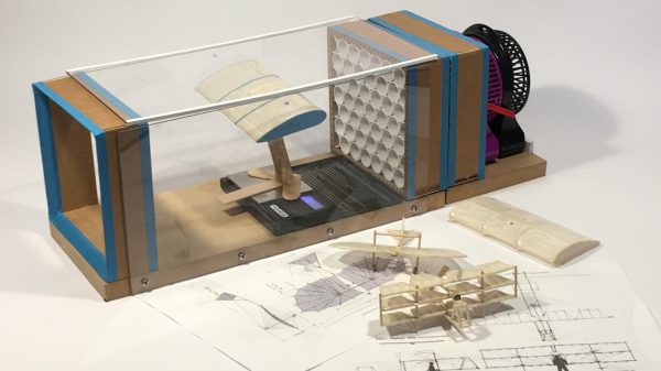
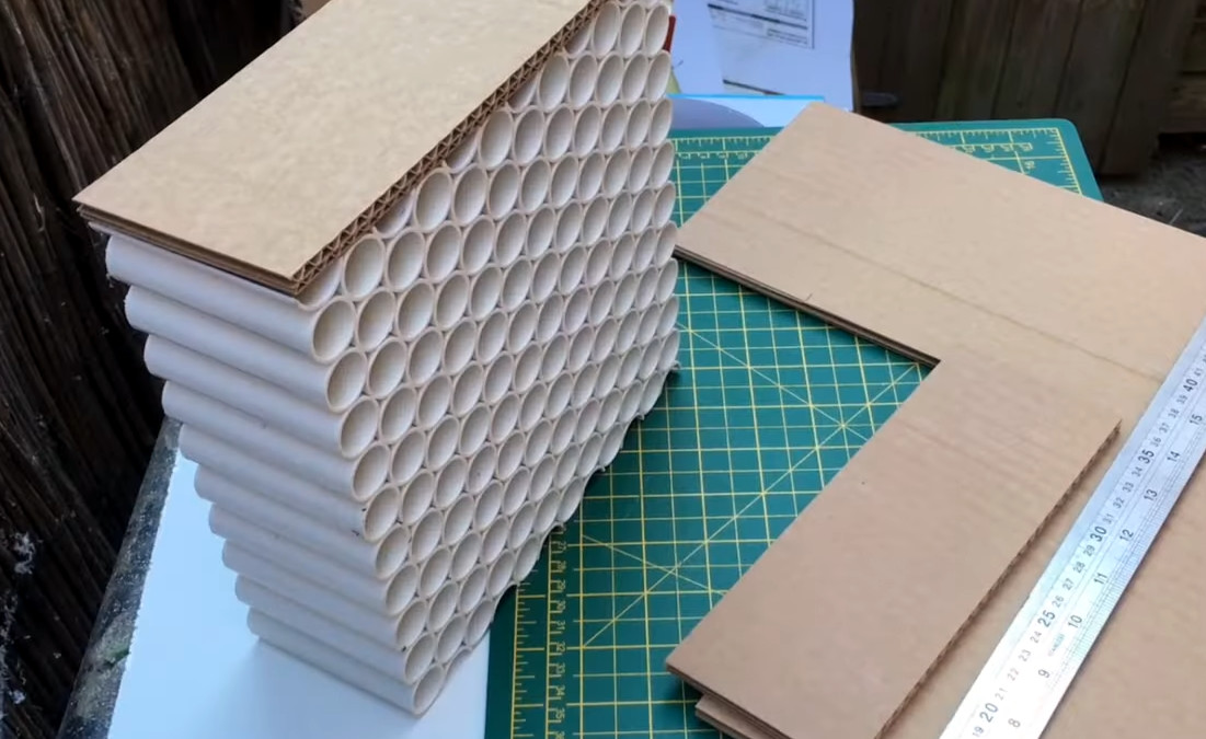
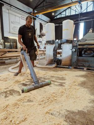
Intended for high school Design & Technology (D&T) classes, it uses relatively simple materials construction techniques. The airflow straightener is built out of PVC pipes, and the end boxes built out of cardboard. The transparent walls for observation are created out of acrylic, while a simple fan provides the necessary flow. The desk-sized wind tunnel can then be instrumented with a manometer, tachometer, and anemometer to measure pressure, fan speed, and wind speed. [Jude] also explores experiments that can be run in the wind tunnel, such as working with a small balsa wood glider and measuring the lift it generates with a scale.

[Jude] has a very pragmatic and real-world understanding of such projects, too. He notes the difference between making things to measure, and making them to fit, and highlights the values of both approaches. It’s a much more holistic approach than simply berating students to “do it right” or “do it better” when making things in a D&T class.

Use of a basic wind tunnel is often not taught to engineering students until at least the second or third year of an engineering degree, after all the boring math and static analysis has been dealt with. However, there’s no reason high school physics students can’t understand the physics involved, and they’re more than capable of undertaking such a build. Starting such education early often nets huge benefits for individuals and their eventual careers.

Once you’ve got yourself a wind tunnel, you might want to start thinking about some flow visualization, which gets really exciting.

Continue reading “DIY Wind Tunnel Aims To Educate The Youth”

Unintentional Emissions

First, it was the WiFi router: my ancient WRT54G that had given me nearly two decades service. Something finally gave out in the 2.4 GHz circuitry, and it would WiFi no more. Before my tears could dry, our thermometer went on the fritz. It’s one of those outdoor jobbies that transmits the temperature to an indoor receiver. After that, the remote for our office lights stopped working, but it was long overdue for a battery change.

Meanwhile, my wife had ordered a new outdoor thermometer, and it too was having trouble keeping a link. Quality control these days! Then, my DIY coffee roaster fired up once without any provocation. This thing has worked quasi-reliably for ten years, and I know the hardware and firmware as if I had built them myself – there was no way one of my own tremendously sophisticated creations would be faulty. (That’s a joke, folks.) And then the last straw: the batteries in the office light remote tested good.

We definitely had a poltergeist, a radio poltergeist. And the root cause would turn out to be one of those old chestnuts from the early days of CMOS ICs – never leave an input floating that should have a defined logic level. Let me explain.

The WRT54G was the hub of my own home automation system, an accretion of ESP8266 and other devices that all happily speak MQTT to each other. When it went down, none of the little WiFi nodes could boot up right. One of them, described by yours truly in this video, is an ESP8266 connected to a 433 MHz radio transmitter. Now it gets interesting – the thermometers and the coffee roaster and the office lights all run on 433 MHz.

Here’s how it went down. The WiFi-to-433 bridge failed to connect to the WiFi and errored out before the part of the code where it initialized GPIO pins. The 433 MHz transmitter was powered, but its digital input was left flopping in the breeze, causing it to spit out random data all the time, with a pretty decent antenna. This jammed everything in the house, and apparently even once came up with the command to turn on the coffee roaster, entirely by chance. Anyway, unplugging the bridge fixed everything.

This was a fun one to troubleshoot, if only because it crossed so many different devices at different times, some homebrew and some commercial, and all on different control systems. Until I put it together that everything on 433 MHz was failing, I hadn’t even thought of it as one event. And then it turns out to be a digital electronics classic – the dangling input!

Anyway, hope you enjoyed the ride. And spill some copper for the humble pull-down resistor.

Lamp Flashing Module Is Perfect For Automotive Use

Modern cars tend to have quite advanced lighting systems, all integrated under the control of the car’s computer. Back in the day, though, things like brake lights and indicators were all done with analog electronics. If your classic car needs a good old-fashioned flasher module, you might find this build from [DIY Guy Chris] useful.

It’s an all-analog build, with no need for microcontrollers or other advanced modern contrivances. Instead, a little bipolar PNP transistor and a beefier NPN MOSFET as an oscillator, charging and discharging a capacitor to create the desired flashing behavior. Changing the size of the main capacitor changes the flash rate. The MOSFET is chosen as running 12 volt bulbs requires a decent amount of current. The design as drawn is intended to run up to eight typical automotive bulbs, such as you might find in indicator lamps. However, [Chris] demonstrates the circuit with just four.

Flasher circuits were in regular use well into the 1990s. The original Mazda Miata has a very similar circuit tucked up under the dashboard to run the turn signals. These circuits can be hard to find for old cars, so building your own may be a useful workaround if you’re finding parts hard to come by. Video after the break.

Continue reading “Lamp Flashing Module Is Perfect For Automotive Use”

DVD Drives Turned Into Microscopes

With the advent of streaming services, plenty of people are opting to forego the collection of physical media. In turn, there are now a lot of optical drives sitting unused in parts bins and old computers. If you’d like something useful to do with this now-obsolete technology, you can have a try at turning one into a laser microscope.

This build requires two DVD pickups. By scanning once horizontally and once vertically and measuring the returning light from the DVD laser, an image can be created. For this build, the second pickup is used to move the object itself. The entire device is controlled by an Analog Discovery 2, although this principle could be ported to other microcontroller platforms. Thanks to the extremely fine laser in a DVD and the precise movements of the motors found in the control machinery, the images obtained using this method have the potential to be more detailed than comparable visible light microscopes.

While this isn’t quite scanning electron microscope territory, it’s good enough to clearly image the internal workings of a de-capped integrated circuit. Something like this could be indispensable for reverse-engineering ICs or troubleshooting other comparably small electronics, with resolutions higher than can typically be obtained with visible light microscopes. We’ve even seen similar builds in the past which build microscopes like this as dedicated lab equipment.

A High-Powered Vacuum Cleaner For Tough Jobs

Vacuum cleaners are great for tidying up the home, but they typically can’t deal with the bulky, gross messes of a proper workshop. [CraftAndu] is currently building a sailing vessel, and has found that there’s simply too much sawdust for a regular vacuum to take on. Thus, he built a mighty vacuum of his own that’s able to deal with such conditions.

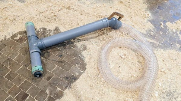
The core of the build is a giant 3.8 kW dust collector that’s used as part of a workshop dust extraction system. It’s of the type you’d normally use to suck up dust from machine tools. It’s then fitted with a long flexible hose that goes to the vacuum handle itself. The handle is made up of lengths of sewage pipe and several adaptors to fit it all together and hook up to the flexible tube. It’s also fitted with a set of wheels to allow it to be easily skated about the floor of the shop.

It’s a neat way to suck up all the lightweight sawdust that collects around the workshop. However, [CraftAndu] notes that even with the 3.8 kW extraction system powering it, it’s still quicker to use a broom for bigger detritus like wood chips and the like.

A lot of people think that vacuum projects suck, but we’ve always had a soft spot for them. Pun intended, and you’ll find the video after the break!

Continue reading “A High-Powered Vacuum Cleaner For Tough Jobs”

Make Your Own Color Gradient 3D Printing Filament

Color gradient filament is fun stuff to play with. It lets you make 3D prints that slowly fade from one color to another along the Z-axis. [David Gozzard] wanted to do some printing with this effect, and learned how to make his own filament to do the job. 

[David] intended to 3D print a spectrogram of a gravity wave, and wanted the graph to go from blue to yellow. Only having a single-color printer, he needed color shift filament, but couldn’t find any blue-to-yellow filament online.

The resulting color-shifting print looks great, demonstrating the value of the technique.

Thus, he elected to create it himself. He started by creating a spiral model in Fusion 360, with a hexagonal cross-section and slowly tapering off to a point. Slicing and printing this in blue results in a filament that slowly fades down to a point. The opposite shape can then be printed in yellow, tapering from a point up to a full-sized filament. The trick is to print one shape, then the other, by mashing the G-code together and changing the filament from blue to yellow along the way. The result is the blue and yellow plastic gets printed together into a single filament that gradually changes from one to the other.

Notably, the filament is smaller than the original filaments used to create it, so it’s necessary to run slightly different settings when using it. [David] has shared the models on Thingiverse for those eager to recreate the technique at home. His resulting gravity wave print is impressive, demonstrating that this technique works well!

We’ve seen similar different techniques used for creating multi-color filaments before, too. Video after the break.

Continue reading “Make Your Own Color Gradient 3D Printing Filament”

New controller PCB shown below the original one. The new PCB has an ESP module with an antenna, a lot of support circuitry, and all the same connectors that the original board does.

Controller For 946C Hotplate Adds Reflow Profile Upload Over BLE

Reflow hotplates are a wonderful tool for PCB assembly if you can keep your designs single-sided. The 946C hotplate in particular has been on hackers’ radar for a while – a 200x200mm working surface hotplate available for under $100 is a decent investment. As with other reflow tools, it was a matter of time until someone made a replacement controller for it. This one, you’ll want to keep in mind – it’s a replacement controller project by [Arnaud Durand] and [Elias Rodriguez Martin], called Reflow946.

Keeping to best practices, the board is a drop-in replacement for the stock controller – swap cables over and go. The host processor is an ESP32, and it lets you can program reflow profiles in using BLE, with a Python application to help. The whole design is open-source and on GitHub, of course – keeping with best 3D printing traditions, you can already order the parts and PCBs, and then assemble them using the hotplate you’re about to upgrade. As far as aftermarket controllers go, here’s no doubt this board gives you way more control in reflow and lets you compensate for any possible subpar calibration while at it. Continue reading “Controller For 946C Hotplate Adds Reflow Profile Upload Over BLE”