Modern Microcontroller Boosts Classic Logic Analyzer To New Heights

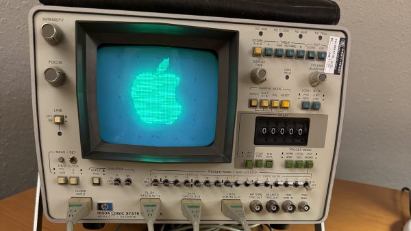
[Ted Fried] recently found a beautiful HP 1600A/1607A logic analyzer set. State of the art in 1975, it looks like glorious Space Age equipment today. He decided to hook it up some modern gear to put it through its paces.

Wanting to give the equipment a proper shakedown, he enlisted a Teensy 4.1 to spit a deluge of logic at the HP unit. The microcontroller was tasked with generating 32 data signals along with two clock outputs to give the analyzer plenty to analyze. The HP 1600A handled this no problem, so [Ted] kept tinkering.

His next feat was to explore the addressable “MAP” function of the unit, which allowed writing to the 64×64 pixel display. The Teensy 4.1 was easily able to send images to the display, but [Ted] isn’t stopping there. He’s got plans to do the usual thing and get Bad Apple going on the hardware.

Getting a logic analyzer to analyze logic isn’t much of a hack, sure. But it’s instructive of how to approach working with such hardware. If you want to spit a bunch of logic out fast, a Teensy 4.1 is a great choice because it’s got a ton of IO and a ton of clock cycles to tickle it with.

We enjoyed seeing this old piece of hardware light up the phosphors once more. If you’ve got your own projects going on with classic bits of HP test gear, don’t hesitate to let us know!

A DIY handheld PONG game

DIY Pocket PONG Breaks The Mobile Spell

[Minikk], aka [Athul] is about to enter 10th grade and reports that they and their contemporaries are eschewing boring mobile games for 90s stuff and old games like PONG. Well, we already knew the 90s were back, but it’s nice to see that even older stuff is coming along with it. The kids are alright.

Whether you want to play alone or with a friend, it’s a classic to have in your pocket for sure. The brains behind this 70s-era operation is a Seeed Xiao ESP32-C3, which takes input from the two potentiometers and outputs the game on a 128 x 64 OLED. There’s also a small buzzer for when the ball hits the paddle, or you or your friend slips one past the goalie.

Our favorite part of this build has to be the DIY rivets that hold the OLED in place. [Athul] built posts into the enclosure that get heat-smashed into place with a soldering iron. Pretty neat, huh?

PONG is a specific thrill, certainly. How can it be more thrilling? Maybe with LEDs instead of a screen? Just a thought.

Learn AI Via Spreadsheet

While we’ve been known to use and abuse spreadsheets in the past, we haven’t taken it to the level of [Spreadsheets Are All You Need]. The site provides a spreadsheet version of an “AI” system much like ChatGPT 2. Sure, that’s old tech, but the fundamentals are the same as the current crop of AI programs. There are several “lesson” videos that explain it all, with the promise of more to come. You can also, of course, grab the actual spreadsheet.

The spreadsheet is big, and there are certain compromises. For one thing, you have to enter tokens separately. There are 768 numbers representing each token in the input. That’s a lot for a spreadsheet, but a modern GPT uses many more.

Continue reading “Learn AI Via Spreadsheet”

Faux Silkscreen On A PCB Made With A Laser Cutter

If you’re getting PCBs professionally made, silkscreen usually comes free as part of the package. However, if you’re making your own, the job is on you. [Tony Goacher] makes his own PCBs on a CNC router, so he’s not getting any silkscreening as part of that bargain. But he wondered—could he do something analogous with a laser cutter?

The answer is yes. The silkscreen layer was first exported from DesignSpark, with the file then sent to LightBurn to prep it for laser cutting. The board outline layer was first engraved on to a piece of scrap as an alignment aid. Then, the board was placed in the laser cutter, with the silkscreen scorched directly on to the fiberglass.

The results are encouraging, if imperfect. [Tony] says he ran at “quite fast speed at quite high power.” The markings are all there, but they’re a little melty and difficult to read. He noted at lower speeds and lower power, the results were a bit more readable.

PCBs aren’t really an ideal engraving or laser marking material, but this technique could be servicable for some basic markings on DIY PCBs. We look forward to seeing how [Tony] improves the process in future. Video after the break.
Continue reading “Faux Silkscreen On A PCB Made With A Laser Cutter”

Using A Framework Mainboard For A Custom Gaming Handheld

The nearly final prototype case for the handheld Framework-based gaming system. (Credit: TommyB, YouTube)

Building your own handheld gaming console has been a popular project for many years, but recently it has become significantly easier to get a lot of power into a small package. Like many others, [TommyB] made his own Raspberry Pi SBC-based handheld in the past, which results in a rather bulky and underpowered package. A more performant solution would be to stuff laptop guts into a handheld case, but until Framework came onto the scene this wasn’t easy and would get you a sloppy one-off solution. With [TommyB]’s current handheld project he uses a standard Framework laptop mainboard, along with the official battery to get a very capable gaming system.

Getting the ergonomics and fit for the components just right took many tries, but eventually a prototype shell was designed that fits the Framework mainboard, the battery, twin Framework speakers, an 8″ LCD panel from Waveshare (connected via USB-C to HDMI) and mechanical switches for the buttons. These switches connect to an RP2040-based board that runs the GP2040-CE firmware, allowing the operating system to detect it as an XBox controller. Although still far from finished, it shows just how beneficial standard laptop parts are, with a massive gap in the market where Framework could make its own handheld shell available. We’re looking forward to [TommyB] demonstrating the finished version of his Framework handheld, and the inevitable upgrade from the 11th-gen Intel mainboard to one of the sparkling new mainboards with even better specs.

Thanks to [Keith Olson] for the tip.

Continue reading “Using A Framework Mainboard For A Custom Gaming Handheld”

Proper Routing Makes For Many Happy Return Paths

Here’s a question for you: when your PCB has a ground plane layer, where do return signals flow? It seems like a trick question, but as [Kristof Mulier] explains, there’s more to return path routing (alternate link in case you run into a paywall) than just doing a copper pour and calling it a day.

Like so many other things in life, the answer to the above question is “it depends,” and as [Kristof] ably demonstrates in this concise article, the return path for a signal largely depends on its frequency. He begins by explaining current loop areas and how they factor into the tendency for a circuit to both emit and be susceptible to electromagnetic noise. The bigger the loop area, the worse things can get from a noise perspective. At low frequencies, return signals will tend to take the shortest possible path, which can result in large current loop areas if you’re not careful. At higher frequencies, though, signals will tend to follow the path of minimal energy instead, which generally ends up being similar to the signal trace, even if it has a huge ground plane to flow through.

Since high-frequency signals naturally follow a path through the ground plane that minimizes the current loop, that means the problem takes care of itself, right? It would, except that we have a habit of putting all kinds of gaps in the way, from ground plane vias to isolation slots. [Kristof] argues that this can result in return paths that wiggle around these features, increasing the current loop area to the point where problems creep in. His solution? Route all your signal return paths. Even if you know that the return traces are going to get incorporated into a pour, the act of intentionally routing them will help minimize the current loop area. It’s brilliantly counterintuitive.

This is the first time we’ve seen the topic of high-frequency return paths tackled. This succinct demonstration shows exactly how return path obstructions can cause unexpected results.

Thanks to [Marius Heier] for the tip.

The F Number On A Lens Means Something? Who Knew!

The Raspberry Pi has provided experimenters with many channels of enquiry, and for me perhaps the furthest into uncharted waters it has led me has come through its camera interface. At a superficial level I can plug in one of the ready-made modules with a built-in tiny lens, but as I experiment with the naked sensors of the HD module and a deconstructed Chinese miniature sensor it’s taken me further into camera design than I’d expected.

I’m using them with extra lenses to make full-frame captures of vintage film cameras, in the first instance 8 mm movie cameras but as I experiment more, even 35 mm still cameras. As I’m now channeling the light-gathering ability of a relatively huge area of 1970s glass into a tiny sensor designed for a miniature lens, I’m discovering that maybe too much light is not a good thing. At this point instead of winging it I found it was maybe a good idea to learn a bit about lenses, and that’s how I started to understand what those F-numbers mean.

More Than The Ring You Twiddle To Get The Exposure Right

lose-up of the end of a lens, showing the F-number range
The F-number range of a 1990s Sigma consumer-grade zoom lens.

I’m not a photographer, instead I’m an engineer who likes tinkering with cameras and who takes photographs as part of her work but using the camera as a tool. Thus the f-stop ring has always been for me simply the thing you twiddle when you want to bring the exposure into range, and which has an effect on depth of field.

The numbers were always just numbers, until suddenly I had to understand them for my projects to work. So the first number I had to learn about was the F-number of the lens itself. It’s usually printed on the front next to the focal length and expressed as a ratio of the diameter of the light entrance to the lens focal length. Looking around my bench I see numbers ranging from 1:1 for a Canon 8mm camera to 1:2.8 for a 1950s Braun Paxette 35 mm camera, but it seems that around 1:1.2 is where most 8 mm cameras sit and 1:2 is around where I’m seeing 35 mm kit lenses. The F-stop ring controls an adjustable aperture, and the numbers correspond to that ratio. So that 1:2 kit lens is only 1:2 at the F2 setting, and becomes 1:16 at the F16 setting.

Continue reading “The F Number On A Lens Means Something? Who Knew!”