38C3: Xobs On Hardware Debuggers

If you just want to use a debugger for your microcontroller project, you buy some hardware device, download the relevant driver software, and fire up GDB. But if you want to make a hardware debugger yourself, you need to understand the various target chips’ debugging protocols, and then you’re deep in the weeds. But never fear, Sean [Xobs] Cross has been working on a hardware debugger and is here to share his learnings about the ARM, RISC-V, and JTAG debugging protocols with us.

He starts off with a list of everything you need the debugger hardware to be able to do: peek and poke memory, read and write to the CPU registers, and control the CPU’s execution state. With that simple list of goals, he then goes through how to do it for each of the target chip families. We especially liked [Xobs]’s treatment of the JTAG state machine, which looks pretty complicated on paper, but in the end, you only need to get it in and out of the shift-dr and shift-ir states.

Continue reading “38C3: Xobs On Hardware Debuggers”

Wire Rope: Never Saddle A Dead Horse

If you’re into building large projects, you’ll eventually find yourself looking at wire rope. Multistrand steel wire used as antenna guy wires, bridge supports, and plenty of other uses.  The [HowNot2] team tested an old rule of thumb for wire rope. “Never saddle a dead horse”.

Click through the break for more:

Continue reading “Wire Rope: Never Saddle A Dead Horse”

A Die-Level Look At The Pentium FDIV Bug

The early 1990s were an interesting time in the PC world, mainly because PCs were entering the zeitgeist for the first time. This was fueled in part by companies like Intel and AMD going head-to-head in the marketplace with massive ad campaigns to build brand recognition; remember “Intel Inside”?

In 1993, Intel was making some headway in that regard. The splashy launch of their new Pentium chip in 1993 was a huge event. Unfortunately an esoteric bug in the floating-point division module came to the public’s attention. [Ken Shirriff]’s excellent account of that kerfuffle goes into great detail about the discovery of the bug. The issue was discovered by [Dr. Thomas R. Nicely] as he searched for prime numbers. It’s a bit of an understatement to say this bug created a mess for Intel. The really interesting stuff is how the so-called FDIV bug, named after the floating-point division instruction affected, was actually executed in silicon.

We won’t presume to explain it better than [Professor Ken] does, but the gist is that floating-point division in the Pentium relied on a lookup table implemented in a programmable logic array on the chip. The bug was caused by five missing table entries, and [Ken] was able to find the corresponding PLA defects on a decapped Pentium. What’s more, his analysis suggests that Intel’s characterization of the bug as a transcription error is a bit misleading; the pattern of the missing entries in the lookup table is more consistent with a mathematical error in the program that generated the table.

The Pentium bug was a big deal at the time, and in some ways a master class on how not to handle a complex technical problem. To be fair, this was the first time something like this had happened on a global scale, so Intel didn’t really have a playbook to go by. [Ken]’s account of the bug and the dustup surrounding it is first-rate, and if you ever wanted to really understand how floating-point math works in silicon, this is one article you won’t want to miss.

A Review That Asks: Do You Need A Thermal Camera?

[Maker’s Fun Duck] has a recent video review of a cheap thermal camera from a company called Kaiweets, which you can see below. It checked all of his boxes: It was standalone, handheld, cheap, and not too cheap. The question is: does it work well for the kinds of things we would do with such a camera?

That’s a tricky question, of course, because everyone’s uses are different. Considering a soldering iron. A tiny one is great for working on PCBs, but lousy for soldering large coax connectors. A soldering gun works well for that purpose, but is too much for the PCB. The same goes for thermal cameras. Some are great for, for example, finding leaky parts of houses, but might not be so great at locating defective components on a PCB.

Continue reading “A Review That Asks: Do You Need A Thermal Camera?”

The Business Card Of DOOM

This account of running DOOM on a PCB business card isn’t really about serving the “Will it DOOM?” meme of getting the classic game to run on improbable hardware. Rather, this project has more to do with getting it done right and leveraging work that’s already been done.

We’ll explain. You may recall [rsheldiii]’s previous DOOM keycap build, which was quite an accomplishment for someone who doesn’t fancy himself a hardware hacker. But he made a fair number of compromises to pull that build off, and rather than letting those mistakes propagate, he decided to build a more general platform to serve as a jumping-off point for the DOOM building community. The card is centered on the RP2040, which keeps things pretty simple. The card has a tiny LCD screen along with USB jacks for power and a keyboard, so you can actually play the game. It also has GPIO lines brought out to pads on the edge of the board, in case you want to do something other than play the game, which is shown in the brief video below.

Pretty standard stuff, right? Perhaps, but where this project stands out for us is that it stresses the importance of relying on reference circuits. We’ve all seen projects that have been derided for pulling the example circuit from the datasheet, but as [rsheldiii] points out, that seems a little wrongheaded. Component manufacturers put a lot of effort into those circuits, and they don’t do it out of the goodness of their hearts. Yes, they want to make it easier for engineers to choose their parts, but in doing so they’ve done a lot of the work for you. Capitalizing on that work wherever possible only makes sense, and in this case the results were perfect for the task at hand.

Continue reading “The Business Card Of DOOM

Porting Dragon’s Lair To The Game Boy Color Was A Technical Triumph

If you remember the 80s arcade game Dragon’s Lair, you probably also remember it was strikingly unlike anything else at the time. It didn’t look or play like anything else. So it might come as a surprise that it was ported to Nintendo’s Game Boy Color, and that took some doing!

Dragon’s Lair used LaserDisc technology, and gameplay was a series of what we’d today call quick-time events (QTE). The player essentially navigated a series of brief video clips strung together by QTEs. Generally, if the player chose correctly the narrative would progress. If they chose poorly, well, that’s what extra lives (and a stack of quarters) were for.

More after the break!

Continue reading “Porting Dragon’s Lair To The Game Boy Color Was A Technical Triumph”

Full Color 3D Printing With PolyDye And Existing Inkjet Cartridges

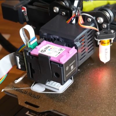
The PolyDye system installed on an Elegoo Neptune 2 printer. (Credit: Teaching Tech, YouTube)

Being able to 3D print FDM objects in more than one color is a feature that is rapidly rising in popularity, assisted by various multi-filament systems that allow the printer to swap between differently colored filaments on the fly. Naturally, this has the disadvantage of being limited in the number of colors, as well as wasting a lot of filament with a wipe tower and filament ‘poop’. What if you could print color on the object instead? That’s basically what the community-made PolyDye project does, which adds an inkjet cartridge to an existing FDM printer.

In the [Teaching Tech] video the PolyDye technology is demonstrated, which currently involves quite a few steps to get the colored 3D model from the 3D modelling program into both OrcaSlicer (with custom profile) and the inkjet printing instructions on the PolyDye SD card. After this the 3D object will be printed pretty much as normal, just with each layer getting a bit of an ink shower.

Although it could theoretically work with any FDM printer, currently it’s limited to Marlin-based firmware due to some prerequisites. The PolyDye hardware consists of a main board, daughter board, printed parts (including inkjet cartridge holder) and some wiring. A Beta Test unit is available for sale for $199, but you should be able to DIY it with the files that will be added to the GitHub project.

Even for a work-in-progress, the results are quite impressive, considering that it only uses off-the-shelf translucent filament and inkjet cartridges as consumables. With optimizations, it could give multi-filament printing a run for its money.

Continue reading “Full Color 3D Printing With PolyDye And Existing Inkjet Cartridges”