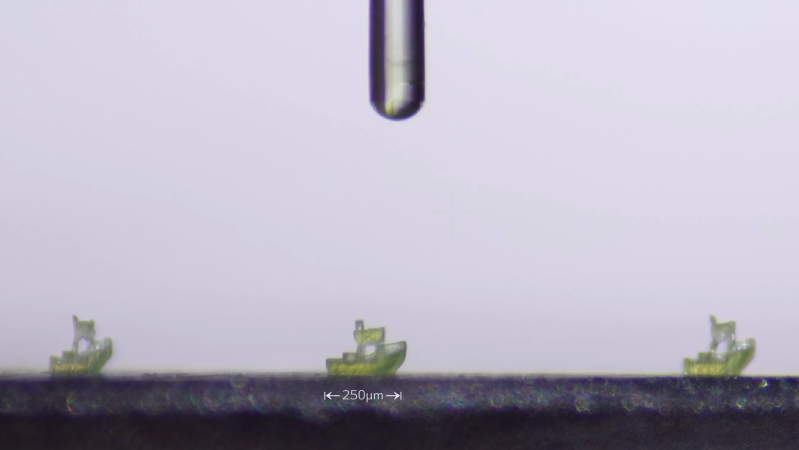
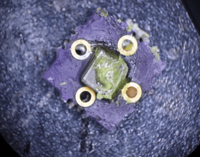
Resin 3D printing has opened up a whole new scale of resolution for hackers, but the technology can go still finer; commercial micro-SLA and two-photon polymerization printers can print items with sub-micron feature sizes, but the machines are well out of reach for hackers. There’s more than one way to get such high resolution, though, as [Diffraction Limited] demonstrated with his micron-scale resin printer.
The printer builds on [Diffraction Limited]’s previous micro-manipulator and fiber-coupled laser. The micro-manipulator holds the end of the optical fiber just in front of the build plate, which is coated with resin. A 405-nm laser shines through the fiber, curing the resin in a narrow cone in front of the fiber’s core, which the micro-manipulator can trace in a pattern to build up objects, much like an FDM printer. Since the fiber’s inner core is only three microns across, the cured resin shears cleanly away from it when the fiber moves. Since the principle is so similar to an FDM printer, a standard slicer could be used to generate the tool paths.
Driven by a desire for privacy, customization, and lower costs, there’s growing interest in AI models which can be run on local hardware. Few of them go as far as [Tim], though, who built an image generation diffusion model which can run on an RP2350 microcontroller.
As might be expected, its capabilities are limited. The resolution is 128×128, it only generates images of human faces, and it takes about twenty seconds per image – still impressive for such limited hardware. It runs on a Waveshare RP2350 development board, and it can output the generated image over USB or display it with the aid of a VGA adapter board.
The generative model doesn’t directly create an image. Rather, it generates a distribution in a latent space, which a variational auto-encoder’s decoder component translates into an image. The auto-encoder was trained in two parts: an encoder which transforms an image into a latent-space distribution, and a decoder to transform that distribution back to an image; once this was trained, only the decoder was used.
The generative portion of the model uses a latent flow diffusion transformer; this takes in noise to start with, then iteratively predicts changes which bring it toward the desired image. It can also take in a output class, which guides the generator’s direction (toward a smiling face, for example). [Tim] trained two models, one larger and one faster, and quantized the weights for both to 8-bit integers. Both models, along with the inference program, then fit into 4 MB of flash memory.
For such a small model, the results are remarkably good; they don’t look quite natural, but they’re quite recognizable. For more on how diffusion image generators work, check out our article on Stable Diffusion.
If you want improve a model rocket’s performance, all the common options come with serious trade-offs: you could increase the motor’s size, which raises safety issues, or you could cut down on weight, which limits the possible payload. [Con Hathy] was therefore intrigued by the design of the Arcas sounding rockets, which with the aid of a gas-fed launch tube could reach an altitude of 100 km. Even in models without a gas generator, a launch tube apparently boosted performance, an effect which [Con] was able to replicate in a much smaller model rocket.
In theory, as the rocket engine fires, it should pressurize the tube behind the rocket, providing an extra boost out of the tube. To test this, [Con] 3D printed a test rocket, launched it both from a standard rail and from a tube, and compared the results. During tube launches, a printed sabot fit around the rocket and formed a seal with the launch tube. The results were surprising: the tube-launched rocket actually performed substantially worse than a rail launch. After building a simulation, [Con] found that, as the rocket moves down the tube, the volume of tube it needs to back-fill with gas increases faster than the engine puts out exhaust; it was pulling a slight vacuum behind it, slowing itself down.
To solve this, [Con] decreased the diameter of the launch tube. To let the rocket fit into the tube, he also modified it to use pop-out stabilizer fins which wrap around the rocket while in the tube. The sabot was also shrunk, and had foam added to improve the seal between it and the rocket. For this second test, [Con] also connected a pressure sensor to the base of the launch tube. The results on the second launch were much better: according to an altimeter, it managed to fly 72% higher. Based on the pressure sensor’s data, a longer tube could have squeezed out still more performance, but this still demonstrated the principle quite well.
We’ve seen a tube-launched rocket before, though not with such a performance focus.
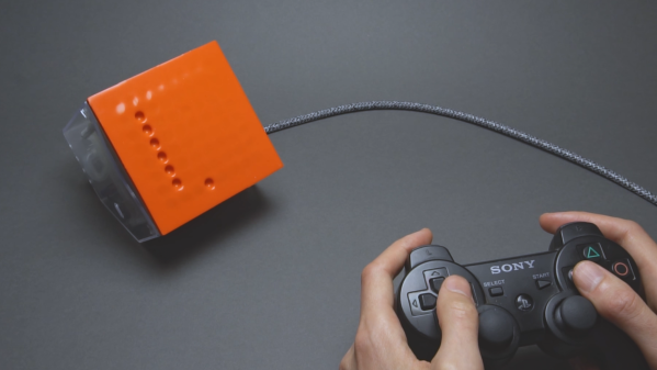
[soiboi soft]’s vacuum-driven dot matrix display is part suction gripper, part touchscreen, and altogether impressive. Its display capabilities are entirely shadow-based, with each pixel being made of a cavity behind a flexible silicone sheet; when the display’s microfluidic logic circuitry activates a pixel, a vacuum pump pulls the sheet inwards, creating a visible hollow.
As in previous iterations, the display’s control circuitry is built around a pneumatic “transistor”, which allows an air channel to be opened or closed by applying vacuum to a control channel. As a first test, [soiboi soft] built a 16-pixel dot matrix display. Eight control channels – four row and four column channels – are multiplexed to individually control each pixel. The transistors act like one-way valves, so the pixels hold their state, even when pressed in by hand; simply add some circuitry to read a pixel’s state, and it would be a fully-functioning touchscreen. The supporting pneumatics also got an upgrade; the solenoid valves now cleanly mount to the back of the board, and the vacuum pump connects via a Luer lock adapter.
The 3D printing used to make certain parts and silicone molds caused issues when scaling up to a 64-pixel display, however. The parts were warping, destroying the seal necessary to keep pixels “on”. To straighten them out, [soiboi soft] pressed the printed part against a flat glass build plate in a vacuum bag and annealed it at 60 Celsius for several hours. This worked quite well, particularly when slightly raised rings were printed around the area to be sealed. Once all these bugs were worked out, the display was clear and decently responsive. [soiboi soft] was able to display letters, numerals, and animations, and even able to play Pong and Snake. It won’t be setting any refresh rate records, but it was nevertheless fully usable.
For another approach to playing Snake with microfluidics, check out this project. If printing molds and casting silicone seems too fiddly, there are always other ways to make microfluidic circuits.
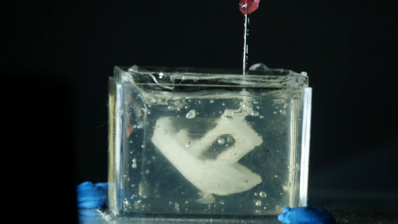
There’s plenty of substances that can theoretically be extruded from a nozzle, but only a regrettably small subset of them can actually be used for 3D printing. One limiting factor is the liquid range: too high a melting point and it’s hard to reliably extrude, too low and it tends to ooze and flow once extruded. Embedded 3D printing offers a way around this: it submerges the entire print in a shear-thinning support gel which keeps liquids in place until they solidify. [Riley] of Riley’s Lab recently built such a 3D printer and used it to print in silicone and epoxy.
In place of the extruder, [Riley] mounted a mostly 3D printed syringe pump, which allowed him to squirt out almost any liquid. For a test, he printed a tardigrade model out of cream cheese. This was a good test material for several reasons: it’s cheap, easy to extrude, and holds it shape well after extrusion. Silicone and epoxy, however, won’t hold their shape, which is where the support bath comes it. This was a mixture of mineral and vegetable oil, with some fumed silica added to make it thick yet shear-thinning. This lets it contain the extruded liquid, yet flow as the extrusion needle slices through it.
For the first test, [Riley] printed a Benchy out of Sylgard 184. The outcome looked good in the bath, bar some stringing, but it seemed to have limited adhesion between layers, and disintegrated upon removal from the bath. A second test with a two-part epoxy worked much better; it also had some stringing, but it held together while the bath was washed away in isopropyl alcohol, and even seemed decently shock-resistant afterwards.
It’s great to see a hacker working on this technology; we’ve previously covered a commercial take on it, as well as some of the research that led to it.
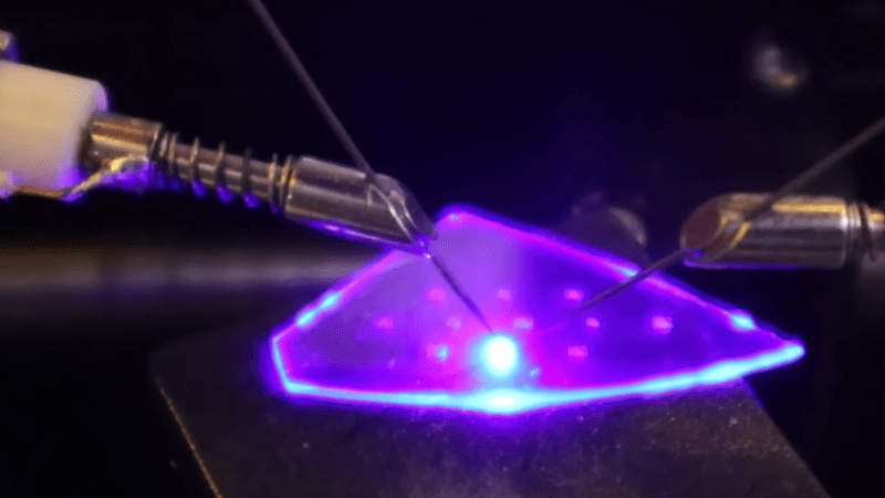
Impressive as it most certainly is when an amateur fabricates a semiconductor, most of the projects we’ve seen are more demonstrations than workable chips. [Dr. Semiconductor], however, is going much further with his fabrication process, and is already working on a method to bond chips to printed circuit boards. It’s difficult to align a PCB with the pads on the underside of an opaque silicon wafer, however, so as a trial run he’s made and bonded some transparent LED chips.
The starting material for these chips is a gallium nitride (GaN) LED epiwafer, a stacked structure of n-doped GaN, an indium gallium nitride quantum well layer, and p-doped GaN grown on a sapphire substrate. When current passes through the structure, electrons from the n-doped layer and holes from the p-type layer recombine in the quantum well layer, emitting blue light. To make a functional LED from this, [Dr. Semiconductor] needed to make electrical contacts to both the n-type and p-type layers. Making the n-type contact required cutting through the p-type and quantum well layers.
This would normally be done with reactive ion etching in chlorine, but [Dr. Semiconductor] came up with a new process: a 355-nm ultraviolet etching laser causes GaN to break down into gallium and nitrogen, with the resulting cut being cleaned up by a potassium hydroxide etch. To deposit the contacts themselves, [Dr. Semiconductor] formed a photoresist mask, deposited metal (nickel, silver, and titanium) in a sputtering chamber, and used a developer solution to dissolve the mask and lift off the unwanted metal regions.
The LED after bonding and phosphor application.
When [Dr. Semiconductor] applied current between the two contacts, the LED glowed bright blue. The next step was to mount it to a PCB; to do so, he first sliced the wafer into individual LED chips with the ultraviolet laser. He then electroplated indium bumps onto a printed circuit board, positioned the chip above these bumps, added some rosin flux, and melted the indium bumps. This soldered the chip to the board and let the board power the LED.
Like most commercial white LEDs, these were blue; most LED assemblies additionally include a phosphor layer which absorbs blue light and emits another color. To create a white LED, for example, [Dr. Semiconductor] mixed cerium-doped yttrium aluminium garnet phosphor powder with clear silicone and spread it over the LED. This absorbs some of the blue light and emits yellow light, and the resulting mixture of blue and yellow light looks white to human eyes.
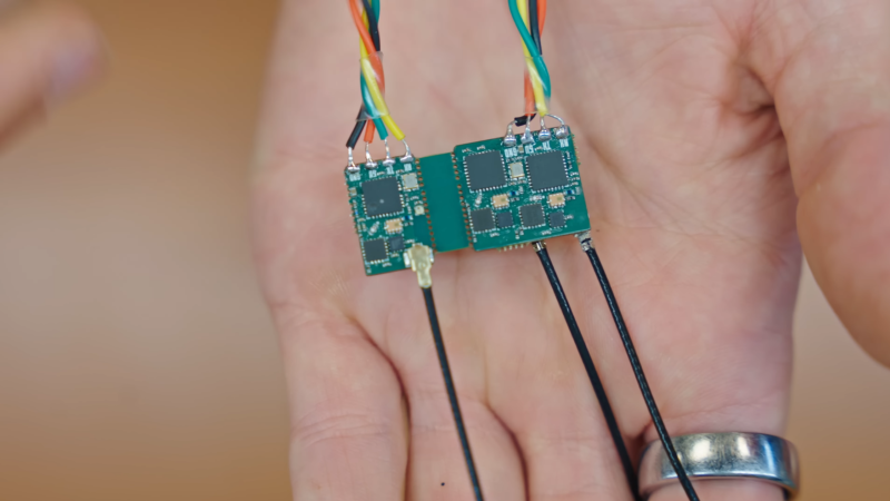
Drone control links are, from a radio signals perspective, nothing short of amazing: using a transmitter capable of transmitting, at most, one watt, a protocol such as ExpressLRS (ELRS) can control a drone over 100 kilometers away. [Stan], who has been building a drone electronics stack from scratch, recently designed four ELRS receivers and went over the principles behind their incredible range.
Up to a certain point, the simplest way to increase a radio’s range is to lower the frequency; lower radio frequencies penetrate better through most materials and don’t attenuate as quickly with distance. However, although ELRS can use 900 MHz bands, [Stan]’s receivers primarily use 2.4 GHz. The major improvement is in modulation: unlike other control protocols, which mostly use frequency modulation, or Wi-Fi, which uses phase and amplitude modulation, ELRS uses Chirp Spread Spectrum modulation. This has a low data rate, but it’s very reliable; every bit is transmitted as a chirp – a linearly rising radio tone – and the data is encoded in the chirp’s starting frequency. To decode this, the receiver multiplies it with an inverse chirp, then takes a fast Fourier transform, revealing the starting frequency. This process has an equivalent gain of 24 dB, which is enough to let it decode signals even below the receiver’s noise floor.
The hardware [Stan] designed to implement this was comparatively simple, just an ESP32 microcontroller, an SX1281 radio chip, and a few peripherals. All four receivers worked in 2.4 GHz, but two had additional 900 MHz antennas. Against RF design convention, one of the receivers used a via to connect the antenna. This would normally cause a significant impedance mismatch, but since there were enough ground-plane vias nearby, the current return path was barely affected; the receiver’s performance hardly changed. In one test, all four receivers maintained a connection at more than five kilometers, despite a forest blocking the signal’s path.