Refreshable Braille Display And Braille Keyboard

Only about 10% of blind people around the world can read Braille. One primary reason is the high cost of Braille displays. The cost is a result of their complexity and reliability – required to ensure that they are able to handle wear and tear.

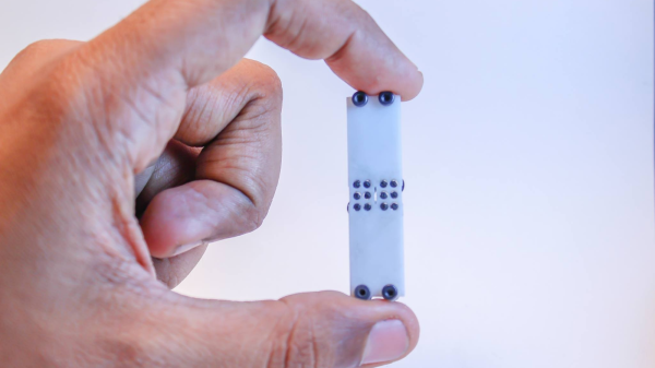
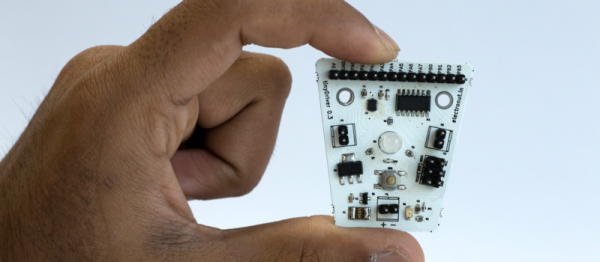
[Vijay] has been working since 3 years on a Refreshable Braille Display but has only recently been able to make some substantial progress after teaming up with [Paul D’souza]. During his initial experiments, he used dot matrix printer heads, but the current version uses tiny vibration motors as used in mobile phones. He’s converting rotary motion of the tiny motors in to linear movement for pushing the Braille “cell” pins up and down. The eccentric weight on the vibration motor is replaced with a shaped cam. Continuous rotation of the cam is limited by a stopper, which is part of the 3D printed housing that holds the motors. Another 3D printed part has three cam followers, levers, springs and Braille pins rolled in one piece, to create half a Braille cell. Depending on the cam position, the pins are either pushed up or down. One Braille cell module consists of two cam follower pieces, a housing for six vibration motors, and a cover plate. Multiple modules are chained together to form the display.

The next step would be to work on the electronics – in particular ensuring that he is able to control the motor movement in both directions in a controlled manner. Chime in with your comments if you have any ideas. The 3D design files are available from his Dropbox folder.

Continue reading “Refreshable Braille Display And Braille Keyboard”

Circuit Bender Artist Bends Fresnel Lens For Art

Give some mundane, old gear to an artist with a liking for technology, and he can turn it into a mesmerizing piece of art. [dmitry] created “red, an optic-sound electronic object” which uses simple light sources and optical elements to create an audio-visual performance installation. The project was the result of his collaboration with the Prometheus Special Design Bureau in Kazan, Russia. The inspiration for this project was Crystall, a reconstruction of an earlier project dating back to 1966. The idea behind “red” was to recreate the ideas and concepts from the 60’s ~ 80’s using modern solutions and materials.

The main part of the art installation consists of a ruby red crystal glass and a large piece of flexible Fresnel lens, positioned in front of a bright LED light source. The light source, the crystal and the Fresnel lens all move linearly, constantly changing the optical properties of the system. A pair of servos flexes and distorts the Fresnel lens while another one flips the crystal glass. A lot of recycled materials were used for the actuators – CD-ROM drive, an old scanner mechanism and old electric motors. Its got a Raspberry-Pi running Pure Data and Python scripts, with an Arduino connected to the sensors and actuators. The sensors define the position of various mechanical elements in relation to the range of their movement. There’s a couple of big speakers, which means there’s a beefy amplifier thrown in too. The sounds are correlated to the movement of the various elements, the intensity of the light and probably the color. There’s two mechanical paddle levers hanging in there, if you folks want to hazard some guesses on what they do.

Check out some of [dmitry]’s earlier works which we featured. Here’s him Spinning a Pyrite Record for Art, and making Art from Brainwaves, Antifreeze, and Ferrofluid.

Continue reading “Circuit Bender Artist Bends Fresnel Lens For Art”

TinyDriver – ATtiny84 Platform Without Arduino

You don’t need an Arduino for everything! Or do you? This is an argument that plays out here quite often. Whatever the outcome, most folks agree that once you’ve dipped your feet in the shallow end of the pool, the real fun is when you dive into the deep end.

[Mahesh Venkitachalam] designed tinyDriver, an experimental Open Source breakout board for the Atmel ATtiny84 chip. His idea was to create a convenient platform which can be used to understand microcontrollers in-depth, by letting users dive under the hood and make use of the various features of the chip such as timers, PWM, interrupts, ADC, and digital I/O. The ATtiny84 is cheap and simple enough for starters. Add a low-cost AVR programmer, install the free and cross-platform avr-gcc and avrdude tool chain, read up the data sheet, learn some C programming and start experimenting. Rinse and repeat and you’ll be a pro at it soon. He’s got a few starter projects documented on his website to get you going.

The hardware is open source, and the Git repository contains the hardware source and example code. If you’re a hardware noob, he’s thoughtfully added a PTC resettable fuse and reverse polarity protection on the board to make sure you don’t release the magic blue smoke prematurely. All of the I/O’s are broken out on a header, and the motor driver and RGB LED can be disabled when not needed. The board isn’t hand-assembly friendly, but he plans to crowd fund it shortly. If you want to move beyond the Arduino platform, projects like the tinyDriver are the way to go.

The HackadayPrize2016 is Sponsored by:

IntelliServo

Servos are extremely versatile actuators used in a large number of applications which need controlled mechanical movement. The usual way of driving them is by using a PWM output from a micro-controller. But if you’re building a robot or a drone which requires a large number of servos, then it makes sense to add smarts directly to the servo.

[Alvaro Ferrán Cifuentes] did just that by building IntelliServo – an add on board which makes regular servos smart by giving them enhanced capabilities as found in high-end versions. His approach is different compared to other takes on this theme. The IntelliServo is designed to replace the electronics in any regular servo and is not limited to any particular make or type. Once upgraded, it’s possible to read the servos position, temperature and current consumption. This allows interesting uses, such as controlling one servo by moving another one, or detecting collision or stalling by monitoring the servo current. Multiple servos can be daisy-chained and controlled over I²C from a micro-controller, or over USB directly from a computer. Each board features an LPC11U24 32-bit Cortex-M0 micro-controller, a DRV8837 motor driver, a TMP36 temperature sensor and a PCA9508 I²C repeater.

The project is open source and the Github repository contains the board design, Arduino library and examples, servo firmware and mechanical parts as well as use instructions. It’s a modular design which allows using either an external controller or running it directly via the on-board micro-USB socket. Check out the videos after the break to see the IntelliServo in action.

Continue reading “IntelliServo”

Bare Metal Media Centre

Sometimes, along comes a build that is simple and bare, and yet exemplifies “hacking” – an art form that uses something in a way in which it was not originally intended. We’ve featured a few Raspberry Pi builds, but this one is less about the Pi and more about putting the rest of the hardware nicely together. [Garage Tech] built this Raspberry-Pi Stand and the end result is brilliant.

MediaPlayerSide-6-5-4It is nothing more than a metal book holder – the kind you are likely to pick up a pair for a few bucks at a charity shop or flea market. He was lucky to also snag a JBL On Stage IIIP Speaker Dock for cheap. Quickly spotting an opportunity, he decided to put together an OpenELEC based media centre using his bounty. Having made up his mind, he needed a couple of other parts to make sure this build looked, and sounded, good. An iQuadio Pi DAC+ , the Pi-DAC+ case from ModMyPi which comes with all the necessary hardware, and the official DSI touch screen.

With all of the stuff on hand, the rest of the build involved a short time at the workbench drilling some holes and slots in the aluminium book holder plate to mount the Pi-DAC case and the display. He drilled the holes and slots such that he can fix the display on either side. Along the way, he discovered an interesting issue regarding the display orientation – check it out. The final result is a nice looking media centre that sits proudly on top of his audio rig.

Two-Sided Laser Etching

[Dan Royer] explains a simple method to engrave/etch on both sides of a material. This could be useful when you are trying to build enclosures or boxes which might need markings on both sides. There are two hurdles to overcome when doing this. The first is obviously registration. When you flip your job, you want it re-aligned at a known datum/reference point.

The other is your flip axis. If the object is too symmetric, it’s easy to make a mistake here, resulting in mirrored or rotated markings on the other side. Quite simply, [Dan]’s method consists of creating an additional cutting edge around your engraving/cutting job. This outline is such that it provides the required registration and helps flip the job along the desired axis.

You begin by taping down your work piece on the laser bed. Draw a symmetrical shape around the job you want to create in your Laser Cutter software of choice. The shape needs to have just one axis of symmetry – this rules out squares, rectangles or circles – all of which have multiple axes of symmetry. Adding a single small notch in any of these shapes does the trick. Engrave the back side. Then cut the “outside” outline. Lift the job out and flip it over. Engrave the front side. Cut the actual outline of your job and you’re done.

Obviously, doing all this requires some preparation in software. You need the back engrave layer, the front engrave layer, the job cut outline and the registration cut outline. Use color coded pen settings in a drawing to create these layers and the horizontal / vertical mirror or flip commands. These procedures aren’t groundbreaking, but they simplify and nearly automate a common procedure. If you have additional tricks for using laser cutters, chime in with your comments here.

Open Source OBD-II Adapter

Automotive diagnostics have come a long way since the “idiot lights” of the 1980s. The current version of the on-board diagnostics (OBD) protocol provides real time data as well as fault diagnostics, thanks to the numerous sensors connected to the data network in the modern vehicle. While the hardware interface is fairly standardized now, manufacturers use one of several different standards to encode the data. [Alex Sidorenko] has built an open source OBD-II Adapter which provides a serial interface using the ELM327 command set and supports all OBD-II standards.

The hardware is built around the LPC1517 Cortex-M3 microprocessor and can accept a couple of different versions. Here’s the PDF schematic, and a set of Gerber files (ZIP archive) for the PCB layout, if you’d like to dig in to it’s internals. The MC33660 ISO K Line Serial Link Interface device is used to provide bi-directional half-duplex communication interface with the micro-controller. Also included is the TJF1051, a high-speed CAN transceiver that provides an interface between the micro controller and the physical two-wire CAN lines on the ODB-II connector. The serial output from the adapter board is connected to a computer using a serial to USB adapter.

The software is written in C++ for the LPCXpresso IDE – a GNU tool chain for ARM Cortex-M processors, but can also be compiled using a couple of other toolchains. He’s got instructions if you’d like to build the firmware from source, or if you’d like to program the adapter via Flash Magic.

We featured [Alex]’s inexpensive PIC based ODB-II interface way back in 2007, so he’s been working on this for a while and has a good grip on what he’s doing.