Headlight Mod For An Audi A3

If you have a car that is getting on in years, it may be missing some of the latest frills and features that the latest models sport. [Muris] has a slightly dated Audi A3 8P which did not have an AUTO setting for the headlights. In the newer models, this feature turns on the headlights when the ambient light falls below a threshold level (overcast conditions or when going through a tunnel), or when the windshield wipers are turned on. The light sensor is integrated behind the rear view mirror in a special mount, requiring an expensive windshield upgrade if he were to opt for the factory retrofit. Instead, he decided to build his own Automatic Headlights Sensor upgrade for his Audi A3.

His local regulations require the car headlights to be on all the time when the vehicle is in motion. So adding this feature may seem moot at first sight. But [Muris] programmed the headlights to be powered at 70% during daytime conditions and switch to 100% when his sensor detects low ambient light conditions. In the power save mode, all of the other non-essential lights (number plate, tail light) are also turned off to hopefully extend their life. He achieved this by using the VCDS (VAG-COM Diagnostic System) – a widely used aftermarket diagnostics tool for VW-Audi Group vehicles. His tiny circuit switches the lights between the two power settings.

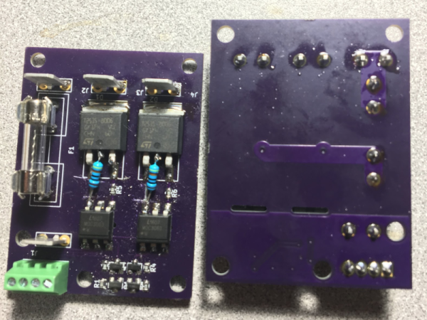
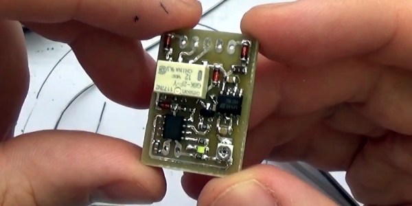
His plan was to install the device without disturbing the original wiring or light switch assembly in any way. The low-powered device consists of a PIC micro-controller, an LDR (light dependent resistor) for light sensing and a low current relay which switches between the two modes. Setting the threshold at which the circuit switches the output is adjusted by a variable trimpot acting as a voltage divider with the LDR. [Muris] wired up a short custom harness which let him install this circuit between the default light switch and the car electronics. After switching on power, he has 15 seconds to enable or disable his unit by toggling the light switch five times, and that status gets stored in memory. The tiny board is assembled using SMD parts and is protected with a heatshrink sleeve. The circuit would work equally well with a lot of other cars, so If you’ve got one which could do with this feature upgrade, then [Muris] has the Eagle CAD files and code available for download on his blog.

Check out the video below where he runs a demo, describes his circuit in detail and then proceeds to assemble the PCB without using a vise or a third hand to hold the PCB. That’s a fancy watch he’s sporting at 00:50 s down the video.

Continue reading “Headlight Mod For An Audi A3”

This Computer Is As Quiet As The Mouse

[Tim aka tp69] built a completely silent desktop computer. It can’t be heard – at all. The average desktop will have several fans whirring inside – cooling the CPU, GPU, SMPS, and probably one more for enclosure circulation – all of which end up making quite a racket, decibel wise. Liquid cooling might help make it quieter, but the pump would still be a source of noise. To completely eliminate noise, you have to get rid of all the rotating / moving parts and use passive cooling.

[Tim]’s computer is built from standard, off-the-shelf parts but what’s interesting for us is the detailed build log. Knowing what goes inside such a build, the decisions required while choosing the parts and the various gotchas that you need to be aware of, all make it an engaging read.

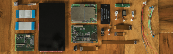
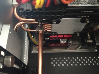
It all starts with a cubic aluminum chassis designed to hold a mini-ITX motherboard. The top and side walls are essentially huge extruded heat sinks designed to efficiently carry heat away from inside the case. The heat is extracted and channeled away to the side panels via heat sinks embedded with sealed copper tubing filled with coolant fluid. Every part, from the motherboard onwards, needs to be selected to fit within the mechanical and thermal constraints of the enclosure. Using an upgrade kit available as an enclosure accessory allows [Tim] to use CPUs rated for a power dissipation of almost 100 W. This not only lets him narrow down his choice of motherboards, but also provides enough overhead for future upgrades. The GPU gets a similar heat extractor kit in exchange for the fan cooling assembly. A fanless power supply, selected for its power capacity as well as high-efficiency even under low loads, keeps the computer humming quietly, figuratively.

Once the computer was up and running, he spent some time analysing the thermal profile of his system to check if it was really worth all the effort. The numbers and charts look very promising. At 100% load, the AMD Ryzen 5 1600 CPU levelled off at 60 ºC (40 ºC above ambient) without any performance effect. And the outer enclosure temperature was 42 ºC — warm, but not dangerous. Of course, performance hinges around “ambient temperature”, so you have to start getting careful when that goes up.

Getting such silence comes at a price – some may consider it quite steep. [Tim] spent about A$3000 building this whole system, thanks in part due to high GPU prices because of demand from bitcoin mining. But cost is a relative measure. He’s spent less on this system compared to several of his earlier projects and it let’s him enjoy the sounds of nature instead of whiny cooling fans. Some would suggest a pair of ear buds would have been a super cheap solution, but he wanted a quiet computer, not something to cancel out every other sound in his surroundings.

Nuclear Synchroscope Gets New Life

The Synchroscope is an interesting power plant instrument which doubles up as two devices in one. If the generator frequency is not matched with the grid frequency, the rotation direction of the synchroscope pointer indicates if the frequency (generator speed) needs to be increased or decreased. When it stops rotating, the pointer angle indicates the phase difference between the generator and the grid. When [badjer1] [Chris Muncy] got his hands on an old synchroscope which had seen better days at a nuclear power plant control room, he decided to use it as the enclosure for a long-pending plan to build a Nixie Tube project. The result — an Arduino Nixie Clock and Weather Station — is a retro-modern looking instrument which indicates time, temperature, pressure and humidity and the synchroscope pointer now indicates atmospheric pressure.

Rather than replicating existing designs, he decided to build his project from scratch, learning new techniques and tricks while improving his design as he progressed. [badjer1] is a Fortran old-timer, so kudos to him for taking a plunge into the Arduino ecosystem. Other than the funky enclosure, most of the electronics are assembled from off-the-shelf modules. The synchroscope was not large enough to accommodate the electronics, so [badjer1] had to split it into two halves, and add a clear acrylic box in the middle to house it all. He stuck in a few LEDs inside the enclosure for added visual effect. Probably his biggest challenge, other than the mechanical assembly, was making sure he got the cutouts for the Nixie tubes on the display panel right. One wrong move and he would have ended up with a piece of aluminum junk and a missing face panel.

Being new to Arduino, he was careful with breaking up his code into manageable chunks, and peppering it with lots of comments, for his own, and everyone else’s, benefit. The electronics and hardware assembly are also equally well detailed, should anyone else want to attempt to replicate his build. There is still room for improvement, especially with the sensor mounting, but for now, [badjer1] seems pretty happy with the result. Check out the demo video after the break.

Thanks for the tip, [Chris Muncy].

Continue reading “Nuclear Synchroscope Gets New Life”

DIY SSR For Mains Switching

Typical power strips have their sockets tightly spaced. This makes it cumbersome to connect devices whose wall warts or power bricks are bulky — you end up losing an adjoining socket or two. And if the strip has a single power switch, you cannot turn off individual devices without unplugging them.

Planning to tackle both problems together, [Travis Hein] built himself some custom Dual SSR Controlled Socket Outlets for his workbench. He also decided to add remote switching ability so he could turn off individual sockets via a controller, Raspberry Pi, smartphone app or most ideally, a nice control panel on his desk consisting of a bank of switches.

The easiest solution for his problem would have been to just buy some off-the-shelf SSR or relay modules and wire them up inside his sockets. But he couldn’t find any with the features he wanted, and SSR’s were a little bit on the expensive side. Also, we wouldn’t have a project to write about – sometimes even the simple ones can show us a thing or two.

For starters, he walks us through a quick and simplified primer on figuring out thermal dissipation for the triacs which will be used on his boards. This is tricky since the devices are connected directly to utility voltage so he needs to take care of track clearances, mechanical separation as well as safety. However, for his first board prototypes, he did not add any heat sinking for the triacs, thereby limiting their use to low current loads. Since the SSR also needs to have a wide control voltage range, he describes how the two transistor constant-current input block works to limit opto-triac LED current over a range of 2 V to 30 V.

Before he moves on to his next prototype, [Travis] is looking for feedback to improve his design, make it safer, and figure out if it can pass safety protocols. Let him know via comments below.

The Solid State Weather Station

Building personal weather stations has become easier now than ever before, thanks to all the improvements in sensors, electronics, and prototyping techniques. The availability of cheap networking modules allows us to make sure these IoT devices can transmit their information to public databases, thereby providing local communities with relevant weather data about their immediate surroundings.

[Manolis Nikiforakis] is attempting to build the Weather Pyramid — a completely solid-state, maintenance free, energy and communications autonomous weather sensing device, designed for mass scale deployment. Typically, a weather station has sensors for measuring temperature, pressure, humidity, wind speed and rainfall. While most of these parameters can be measured using solid-state sensors, getting wind speed, wind direction and rainfall numbers usually require some form of electro-mechanical devices.

The construction of such sensors is tricky and non-trivial. When planning to deploy in large numbers, you also need to ensure they are low-cost, easy to install and don’t require frequent maintenance. Eliminating all of these problems could result in more reliable, low-cost weather stations to be built, which can then be installed in large numbers at remote locations.

[Manolis] has some ideas on how he can solve these problems. For wind speed and direction, he plans to obtain readings from the accelerometer, gyroscope, and compass in an inertial sensor (IMU), possibly the MPU-9150. The plan is to track the motion of the IMU sensor as it swings freely from a tether like a pendulum. He has done some paper-napkin calculations and he seems confident that it will provide the desired results when he tests his prototype. Rainfall measurement will be done via capacitive sensing, using either a dedicated sensor such as the MPR121 or the built-in touch capability in the ESP32. The design and arrangement of the electrode tracks will be important to measure the rainfall correctly by sensing the drops. The size, shape and weight distribution of the enclosure where the sensors will be installed is going to be critical too since it will impact the range, resolution, and accuracy of the instrument. [Manolis] is working on several design ideas that he intends to try out before deciding if the whole weather station will be inside the swinging enclosure, or just the sensors.

If you have any feedback to offer before he proceeds further, let him know via the comments below.

Soundproofing A CNC Mill Conversion

The Proxxon MF70 is a nice desktop sized milling machine with a lot of useful add-on accessories available for it, making it very desirable for a hacker to have one in his or her home workshop. But its 20000 rpm spindle can cause quite the racket and invite red-faced neighbors. Also, how do you use a milling machine in your home-workshop without covering the whole area in metal chips and sawdust? To solve these issues, [Tim Lebacq] is working on Soundproofing his CNC mill conversion.

To meet his soundproof goal, he obviously had to first convert the manual MF70 to a CNC version. This is fairly straightforward and has been done on this, and similar machines, in many different ways over the years. [Tim] stuck with using the tried-and-tested controller solution consisting of a Raspberry Pi, an Arduino Uno and a grbl shield sandwich, with stepper motor drivers for the three NEMA17 motors. The electronics are housed inside the reclaimed metal box of an old power supply. Since the Proxxon MF70 is already designed to accept a CNC conversion package, mounting the motors and limit switches is pretty straightforward making it easy for [Tim] to make the upgrade.

Soundproofing the box is where he faced unknown territory. The box itself is made from wooden frames lined with particle board. A pair of drawer slides with bolt-action locks is used for the front door which opens vertically up. He’s also thrown in some RGB strips controlled via the Raspberry-Pi for ambient lighting and status indications. But making it soundproof had him experimenting with various materials and techniques. Eventually, he settled on a lining of foam sheets topped up with a layer of — “bubble wrap” ! It seems the uneven surface of the bubble wrap is quite effective in reducing sound – at least to his ears. Time, and neighbours, will tell.

Maybe high density “acoustic foam” sheets would be more effective (the ones similar to “egg crate” style foam sheets, only more dense)? Cleaning the inside of the box could be a big challenge when using such acoustic foam, though. What would be your choice of material for building such a sound proof box? Let us know in the comments below. Going back many years, we’ve posted about this “Portable CNC Mill” and a “Mill to CNC Conversion” for the Proxxon MF70. Seems like a popular machine among hackers.

Build Your Own Android Smartphone

Let’s get this out of the way first – this project isn’t meant to be a replacement for your regular smartphone. Although, at the very least, you can use it as one if you’d like to. But [Shree Kumar]’s Hackaday Prize 2018 entry, the Kite : Open Hardware Android Smartphone aims to be an Open platform for hackers and everyone else, enabling them to dig into the innards of a smartphone and use it as a base platform to build a variety of hardware.

When talking about modular smartphones, Google’s Project Ara and the Phonebloks project immediately spring to mind. Kite is similar in concept. It lets you interface hacker friendly modules and break out boards – for example, sensors or displays – to create your own customized solutions. And since the OS isn’t tied to any particular brand flavor, you can customize and tweak Android to suit specific requirements as well. There are no carrier locks or services to worry about and the bootloader is unlocked.

Hackaday Show-n-Tell in Bangalore

At the core of the project is the KiteBoard – populated with all the elements that are usually stuffed inside a smartphone package – Memory, LTE/3G/2G radios, micro SIM socket, GPS, WiFi, BT, FM, battery charging, accelerometer, compass, gyroscope and a micro SD slot. The first version of  KiteBoard was based around the Snapdragon 410. After some subtle prodding at a gathering of hackers in Bangalore, [Shree] moved over to the light side, and decided to make the KiteBoard V2 Open Source. The new board will feature a Snapdragon 450 processor among many other upgrades. The second PCB in the Kite Project is a display board which interfaces the 5″ touchscreen LCD to the main KiteBoard. Of Hacker interest is the addition of a 1080p HDMI output on this board that lets you hook it up to external monitors easily and also allows access to the MIPI DSI display interface.

Finally, there’s the Expansion Board which provides all the exciting hacking possibilities. It has a Raspberry Pi compatible HAT connector with GPIO’s referenced to 3.3 V (the KiteBoard works at 1.8 V). But the GPIO’s can also be referenced to 5 V instead of 3.3 V if you need to make connections to an Arduino, for example. All of the other phone interfaces are accessible via the expansion board such as the speaker, mic, earpiece, power, volume up / down for hacking convenience. The Expansion board also provides access to all the usual bus interfaces such as SPI, UART, I²C and I²S.

To showcase the capabilities of the Kite project, [Shree] and his team have built a few phone and gadget variants. Build instructions and design files for 3D printing enclosures and other parts have been documented in several of his project logs. A large part of the BoM consists of off-the-shelf components, other than the three Kite board modules. If you have feature requests, the Kite team is looking to hear from you.

When it comes to smartphone design, Quantity is the name of the game. Whether you’re talking to Qualcomm for the Snapdragon’s, or other vendors for memory, radios, displays and other critical items, you need to be toeing their line on MOQ’s. Add to this the need to certify the Kite board for various standards around the world, and one realizes that building such a phone isn’t a technical challenge as much as a financial one. The only way the Kite team could manage to achieve their goal is to drum up support and pledges via a Kickstarter campaign to ensure they have the required numbers to bring this project to fruition. Check them out and show them some love. The Judges of the Hackaday Prize have already shown theirs by picking this project among the 20 from the first round that move to the final round.

Continue reading “Build Your Own Android Smartphone”