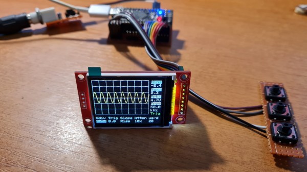
Would you like to have a small digital oscilloscope? Do you have a spare BlackPill (STM32F401) board and a TFT display laying around? [tvvlad1234] presents us with a simple and educational digital storage oscilloscope design that barely needs any components for you to build one, and it’s packed with features just like you would expect from a self-respecting open-source project. Not just that — it can even stream data to your computer, in a format compatible with the TekScope software!
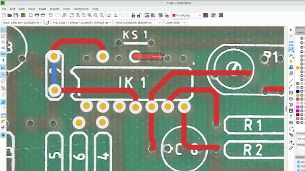
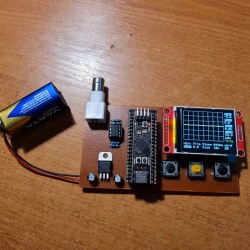 It’s hard to overshadow just how easy this scope is to build, use, and hack on. You really don’t need much in the way of parts, a protoboard will do, though you can also etch or order your own PCBs. The front-end is super straightforward to find components for and assemble, a few opamps and resistors is all you need. So after jumper-wiring the LCD and three push buttons to your BlackPill, you’re golden.
Of course, the simple frontend results in the input range being from -3.3 V to 3.3 V, but as you could guess, this is exactly the kind of project where you could tweak the resistors and even upgrade it later on. Are you a bit lost in how oscilloscopes work? [tvvlad1234] has an explainer for you, too!
This build could easily take up a honorary “temporary turned permanent” place on your bench, thanks to its McGyver-esque qualities. It’s also, quite possibly, a better scope than the red “soldering kit” ones we’ve seen online. All in all, it’s a strong contender in the “simple and powerful DIY scope” arena, before this, we’ve seen one built with an Arduino Nano, and one with a Pi Pico.