A Stack Of Boards For An Edison Breadboard Adapter

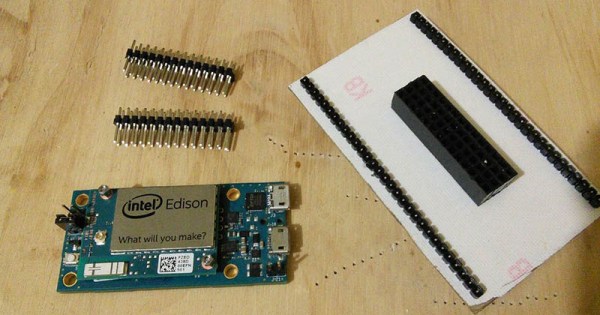
The Intel Edison is a neat piece of hardware, but the connector for the Edison is extremely intimidating and the Mini breakout board is incompatible with breadboards. What’s [Federico], a builder of Internet of Things to do? Etch their own breakout board.

The Mini Breakout board for the Intel Edison is the official ‘minimal’ offering for getting the Edison up and running with a mess of jumper wires and LEDs. While this breakout board handles the USB to UART bridge, power regulation, and exposes all the pins on the Edison connector, it is terrible for prototyping. It’s a 4×14 array of holes on a 0.1″ grid that are hidden underneath the Edison.

[Federico] handled this problem with a copper clad board and a little bit of ferric chloride. He jumped into Eagle and created a breakout board to turn the 4×14 pin grid into a more sensible breadboard-friendly layout.

The breadboard-friendly adapter doesn’t have level shifters, but by using the mini-breakout board between the Edison and the breadboard adapter [Federico] still has the UART to USB hardware and a battery charging circuit. Still, there’s room for improvement and we can’t wait to see what he comes up with next.

The Raspberry Pi Wearable Revolution

With the human URL [will.i.am] serving as Chief Creative Director of 3D Systems, and [Martha Stewart] selling her own line of 3D printer filament through MakerBot, more and more celebrities are piling onto the hacker, maker, and DIY revolution. Now, the partnership we’ve all been waiting for: the Raspberry Pi Foundation and [The Artist Formerly Known As Prince_logo] are teaming up to produce a line of Pi-based wearable electronics. The first product from this new, fashionable line of electronics is beyond anything you would expect. It’s called the Raspberry Beret, and it’s shaping up to be a Revolution in wearables.
The wearable Raspberry Beret is exactly what you would expect: a habadasher’s masterpiece that pairs equally well with figure skating costumes and skin-tight cloud print suits. Inside, though, is a new piece of hardware based on the Raspberry Pi compute module. This module includes a Bluetooth module that will sync with any Windows phone. The Raspberry Beret also includes enough sensors that will blow away everything from a Fitbit to the new Apple Watch. The Raspberet will keep track of your heart rate, activity, and exercise routine.

The Raspberry Beret is just the beginning; the Pi Foundation and [The Artist Formerly Known As Prince_logo] are also teaming up with OSH Park to produce a limited, special edition Raspberry Pi 2. This board will be clad in the beautiful OSH Park purple soldermask and sports 4GB of eMMC Flash. This Flash will not be usable; instead it will contain a remastered edition of Purple Rain that will play as a startup chime. There will be no option to skip the chime.

Pancakes.

Visualizing Digital Logic With EL Wire

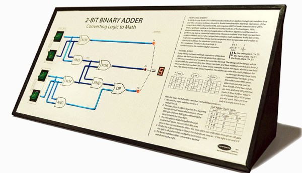
[Bob] and [Aubrey] run the System Source Computer Museum a little north of Baltimore, Maryland. For an exhibit, they thought a visual representation of digital logic and came up with a two-bit binary adder. Yes, it’s just a full adder and exactly what you would find somewhere in the second or third chapter of any digital logic textbook. The way they’re illustrating how a full adder works is the killer feature here: they’re using EL wire for all of the wires connecting the gates.

The full adder is implemented with an Arduino Mega, but the interface is the real show here. On the left side of the display there are four illuminated toggle switches that show virtual electrons flowing through EL wires, through gates and finally out to a seven-segment display. The EL wires are controlled with an EL Escudo Dos shield – a good thing, since there are a lot of lines between switches, gates, and outputs.

You can check out [Aubrey]’s demo video that also shows off how they built it below. If you’re around Baltimore, you can check out the display at the museum.

Continue reading “Visualizing Digital Logic With EL Wire”

Chinese Whispers For Arduino

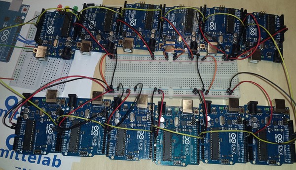
The game of Chinese Whispers or Telephone involves telling one person a sentence, having that person tell another person the same sentence, and continuing on until purple monkey dishwasher. For this year’s Arduino Day, [Mastro] was hanging out at Crunchlab with a bunch of Arduinos. What do you do with a bunch of Arduinos? Telephone with software serial.

The setup for this game is extremely simple – have one Arduino act as the master, listening for bits on the (hardware) serial port. This Arduino then sends those bits down a chain of Arduinos over the software serial port until it finally loops around to the master. The result is displayed in a terminal.

With only about a dozen Arduinos in this game of Telephone, [Mastro] did get a few transmission errors. That’s slightly surprising, as the code is only running at 1200 bps, but the point of this game isn’t to be completely accurate.

Continue reading “Chinese Whispers For Arduino”

New Part Day: Modern PALs

Back in the bad old days, if you needed a little bit of custom logic you would whip out a tiny chip known as a PAL. A Programmable Logic Array is just what it sounds like and is the forerunner of modern, unsolderable CPLDs and FPGAs.

PALs and GALs have died off, left to the wastes of the Jameco warehouse, and now it seems the only programmable logic you can buy are huge, 100-pin monstrosities. [Nick] at Arachnid Labs was working on his Tsunami signal generator when a user asked if they could add just one more feature: a programmable divider to count 256 iterations of a clock. This is the perfect application for dumb logic, but if you’re looking for a part that’s not recommended for new designs, you only need to look to old programmable logic.

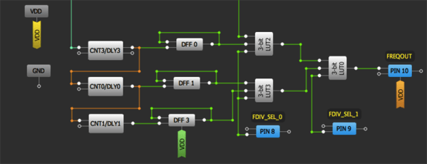
Enter the Greenpak. [Nick] had a dev kit for these ‘modern PALs’ sitting around and decided to give it a go. They’re small – they max out at 20 pins – but there are a few features that make it a little more interesting than a simple array of AND and OR gates. The Greenpak3 features analog comparators, look-up tables, RC oscillators, counters, and GPIO that will work well enough as circuit glue. They also work at 5V, something you’re just not going to find in more complex programmable logic.

These tiny chips are programmed in a graphical IDE, but the datasheet (PDF) includes full documentation for the bitstream; someone needs to write a Verilog or VHDL compiler for it soon. The one downside with these chips is that they’re tiny; 0.4mm pitch QFN packages. If you can solder that, you’re too good at soldering.

Reverse Engineering An RC Spy Tank

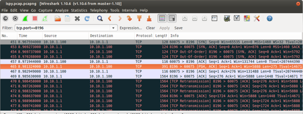
[Michael] sells a remote control spy tank through his company, and although it’s a toy, there’s an impressive amount of electronics in this R/C tank. It’s controlled from an Android or iDevice over a WiFi connection, something that simply won’t do if you’re trying to sell this to the hacker and maker crowd. The solution to this problem is Wireshark, and with a little bit of work this spy tank can be controlled from just about anything, from a microcontroller via WiFi to a Python app.

Wireshark, everyone’s favorite network packet analysis and capture tool, was used to listen in on the communications between an iPad and the tank. This immediately showed the video stream coming from the camera in the tank, and pointing VLC to the correct port displayed the video.

The motors in the tank were a little trickier, but looking at the data stream, a few packets stood out as being responsible for controlling the motors. After a little experimentation the simple command set was decoded and a Python app whipped up.

These spy tanks are cheap – about $70 from [Michael]’s company and the other usual vendors. It’s not a particularly useful piece of hardware, but someone out there is sure to do something cool with this bit of reverse engineering.

Injecting SD Card Bootloaders

[Frank] has a Ultimaker2 and wanted to install a new bootloader for the microcontroller without having physical access to the circuitry. That means installing a new bootloader for the ATMega2560 without an In System Programmer, and as is usual on AVRs, the bootloader can only be edited with an ISP. Additionally, modifying the bootloader in any way runs the risk of corruption and a bricked circuit. That’s okay, because [Frank] knows how to do it, and he’s here to show you how.

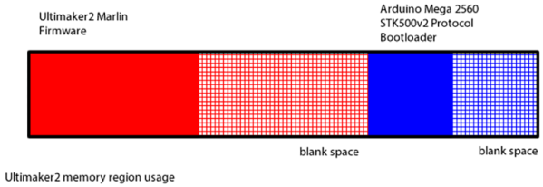
You can think of the memory layout of the ATMega in the Ultimaker as being split in half, with the printer firmware in the first half and the bootloader in the second half. There’s extra space in both halves, and that’s something that comes in very useful. When the circuit powers up, it jumps to the bootloader, does it’s thing, then jumps to the very beginning of the application code – a vector table – that starts up the actual firmware.

[Frank]’s trick to adding on to the bootloader is to place the SD card bootloader in the space normally reserved for applications, not where you would expect to find a bootloader. This code is accessed by the stock bootloader jumping into a modified vector table at the beginning of the application data that points to new executable code. That code is the actual SD card bootloader, but because it is in the application part of the memory, it can’t perform Flash writing or erasing. To fix that, a tiny bit of code is tacked onto the end of the bootloader for performing Flash writes and jumps back to the application part of memory.