Open Data Cam Combines Camera, GPU, And Neural Network In An Artisanal DIY Cereal Box

The engineers and product designers at [moovel lab] have created the Open Data Cam – an AI camera platform that can identify and count objects as they move through its field of view – along with an open source guide for making your own.

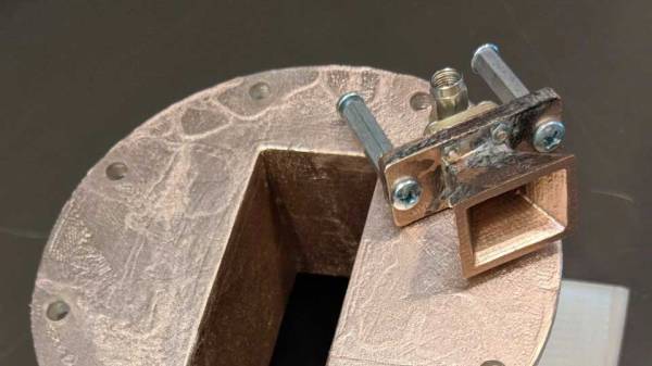
Step one: get out your ruler and utility knife. In this world of ubiquitous 3D-printers they’ve taken a decidedly low-tech approach to the project’s enclosure: a cut, folded, and zip-tied plastic box, with a cardboard frame inside to hold the electronic bits. It’s “splash proof” and certainly cheap to make, but we’re a little worried about cooling and physical protection for the electronics inside, as they’re not exactly cheap and rugged components.

So what’s inside? An Nvidia Jetson TX2 board, a LiPo battery with some charging circuitry, and a standard webcam. The special sauce, however, is the software, which is available on GitHub. [Moovel lab]’s engineers have put together a nice-looking wifi-accessible mobile UI for marking the areas where you’d like the software to identify and tally objects. The actual object detection and identification tasks are performed by the speedy YOLO neural network, a task the Nvidia board’s GPU is of course well suited for.

As the Open Data Cam’s unblinking glass eye gazes upon our urban environments, it will log its observations in an ancient and mysterious language: CSV. It’s up to you, human, to interpret this information and use it for good.

A summary video and build time lapse are embedded after the break.

Continue reading “Open Data Cam Combines Camera, GPU, And Neural Network In An Artisanal DIY Cereal Box”

Blazing Fast Raspberry Pi Display Driver Will Melt Your Face Then Teach You How

Reader [poipoi] recently wrote into our tip line to tell us about an “amazingly fast” Raspberry Pi display driver with a README file that “is an actual joy to read”. Of course, we had to see for ourselves. The fbcp-ili9341 repo, by [juj], seems to live up to the hype! The software itself appears impressive, and the README is detailed, well-structured, educational, and dare we say entertaining?

The driver’s main goal is to produce high frame rates — up to around 60 frames per second — over an SPI bus, and it runs on various Raspberry Pi devices including the 2, 3 and Zero W. Any video output that goes to the Pi’s HDMI port will be mirrored to a TFT display over the SPI bus. It works with many of the popular displays currently out there, including those that use the ILI9341, ILI9340, and HX8357D chipsets.

The techniques that let [juj] coax such frame rates out of a not-terribly-fast serial bus are explained in detail in the README’s How it Works section, but much of it boils down to the fact that it’s only sending changed pixels for each frame, instead of the full screen. This cuts out the transmission of about 50% of the pixels in each update when you’re playing a game like Quake, claims the author. There are other interesting performance tweaks as well, so be sure to check out the repo for all the details.

There’s a video comparing the performance of fbcp-ili9341 to mainline SPI drivers after the break.

Continue reading “Blazing Fast Raspberry Pi Display Driver Will Melt Your Face Then Teach You How”

Use Nodes To Code Loads Of G-code For 3D CNC Carving

Most CNC workflows start with a 3D model, which is then passed to CAM software to be converted into the G-code language that CNC machines love and understand. G-code, however, is simple enough that rudimentary coding skills are all you need to start writing your very own programmatic CNC tool paths. Any language that can output plain text is fully capable of enabling you to directly control powerful motors and rapidly spinning blades.

[siemenc] shows us how to use Grasshopper – a visual node-based programming system for Rhino 3D – to output G-code that makes some interesting patterns and shapes in wood when fed to a ShopBot. Though the Rhino software is a bit expensive and thus is not too widely available, [siemenc] walks through some background, theory, and procedures that could be useful and inspirational no matter what software or programming language you’re using to create your bespoke G-code.

For links to code and related blog posts, plus more lovely pictures of intricately carved plywood, check out [siemenc]’s personal site as well.

[via Bantam Tools]

Soft Robotic Jellyfish Get Pumped In The Atlantic

In a recent paper in Bioinspiration & Biomimetics, researchers at Florida Atlantic University describe the process of building and testing five free-swimming soft robotic jellyfish. The paper contains build details and data on how three different variables – tentacle stiffness, stroke frequency, and stroke amplitude – affect the swimming characteristics of each bot. For a more in-depth build log, we found the original masters thesis by Jennifer Frame to be very thorough, including processes, schematics, parts lists, and even some Arduino code.

Though a landlubber may say the robots look more like a stumpy octopus than a jellyfish, according to the paper the shape is actually most similar to a juvenile “ephyra stage” moon jellyfish, with 8 short tentacles radiating from a central body. The flexible tentacles are made of a silicon rubber material from Smooth-On, and were cast in 3D printed molds. Inside the waterproof main body is a Teensy 3.2 microcontroller, some flash memory, a nine-axis IMU, a temperature sensor, and a 9 V battery.

There are two flexible resistors embedded in the body to measure tentacle flex, and the actual flexing is done by pumping seawater through open circuit hydraulic channels cast into the tentacles. Two 3 V mini pumps are sufficient for pumping, and the open circuit means that when the pumps turn off, the tentacles bleed off any remaining pressure and quickly snap back to their “neutral” position without the use of complicated valves.

Another simple feature is two hall effect sensors that were mounted in the body to enable waterproof “wireless communication” with the microcontroller. The wireless protocol of choice: manually waving magnets over the sensors to switch the robot between a few predefined operating modes.

There’s a soothing, atmospheric video after the break, where you can see the robots in action off the coast of Florida.

Continue reading “Soft Robotic Jellyfish Get Pumped In The Atlantic”

Fully 3D Printed And Metalized Horn Antennas Are Shiny And Chrome

We’ve seen our share of 3D printed antennas before, but none as well documented and professionally tested as [Glenn]’s 3D printed and metalized horn antennas. It certainly helps that [Glenn] is the principal engineer at an antenna testing company, with access to an RF anechoic chamber and other test equipment.

Horn antennas are a fairly simple affair, structurally speaking, with a straight-sided horn-shaped “cone” and a receptacle for standardized waveguide or with an appropriate feed, coaxial adapters. They are moderately directional and can cover a wide range of frequencies. These horns are often used in radar guns and as feedhorns for parabolic dishes or other types of larger antenna. They are also used to discover the cosmic microwave background radiation of our universe and win Nobel Prizes.

[Glenn]’s antennas were modeled in Sketchup Make, and those files plus standard STL files are available for download. To create your own horn, print the appropriate file on a normal consumer-grade fused deposition printer. For antennas that perform well in WiFi frequency ranges you may need to use a large-format printer, as the prints can be “the size of a salad bowl”. Higher frequency horns can easily fit on most print beds.

After printing, [Glenn] settled on a process of solvent smoothing the prints, then metalizing them with commonly available conductive spray paints. The smoothing was found to be necessary to achieve the expected performance. Two different paints were tested, with a silver-based coating being the clear winner.

The full write-up has graphs of test results and more details on the process that led to these cheap, printed antenna that rival the performance of more expensive commercial products.

If you’re interested in other types of 3D printed antenna, we’ve previously covered a helical satcom feed, a large discone antenna, and an aluminum-taped smaller discone antenna.

inside shot of a refrigerator with water bulk tank and seltzer pump

Continuous Seltzer Deployment System Solves Our Bubbly-Water Sourcing Problems

Seltzer water – that bubbly, carbonated water that disappoints sugar-craving children everywhere – has experienced a steady rise in popularity over the past few years. This is perhaps partly fueled by the availability of countertop carbonators such as the SodaStream.

Not satisfied with the tedious and pedestrian process of manually carbonating individual bottles of water, [piyoman] has instead built a tidy little tap of unlimited cold, filtered seltzer. It’s no easy gag. The build uses a commercial carbonator pump, reverse osmosis water filter, bulk tank, and a standard CO2 cylinder to create a constant source of carbonated water. Most of this setup is stuffed into a dorm-sized fridge (tetris-style) and topped with a fancy beer faucet to dispense the resulting bubblewater.

At roughly $800 for the documented system, you need to have a great reason to build your own. But [piyoman] provides detailed instructions, a parts list, and suggestions for cost savings and future improvements if you do take on a system like this for your seltzer needs.

Cheaper Carbonation Options

While looking at how DIY carbonation has been done in the past we found [Richard Kinch’s] Carbonating at Home with Improvised Equipment and Soda Fountains page which dives into many other options. His site – a wonderful, dense demonstration of the beauty of “web 1.0” – walks through the basics of carbonated water, discusses CO2 tanks and gauges, and shows how to build a simple carbonation cap for making seltzer in standard PET soda bottles.