CX-6000 Pen Plotter Upgrade

[Terje Io] decided to breathe new life into an old pen plotter — the CX6000 from C. Itoh, a Japanese company that made several printers for Apple in the 1980s. He keeps most of the framework, but the electronics get a major overhaul. The old motors are replaced, the controller and motor drivers are modernized using a Raspberry Pi Pico and stepper motor drivers. After tending to other auxiliary electronics like the control panel and limit switches, it’s time to deal with the firmware.

Rather than reinvent the wheel, [Terje] sensibly built upon existing projects and refactored them for his application. G-Code processing is done by grblHAL, with an added mode to handle HPGL code. He modified the firmware from Motöri the Plotter project to parse HPGL, making his new CX6000+ bilingual.

We covered Motöri way back in 2009, and more recently we wrote about the Teensy Controller using grblHAL, one of the 32-bit big brothers of GRBL. Have you ever restored one of these old plotters? Or is it easier to just build your own these days?

A Guide To Milling PCBs At Home

If you keep up with various retro vacuum tube projects, you probably have run across [UsagiElectric] aka [David]’s various PCBs that he makes on his own Bridgeport EZ-Track 3-axis milling machine — massively oversized for the job, as he puts it. In a recent video, [David] walks us through the steps of making a sample PCB, introducing the various tools and procedures of his workflow. He points out that these are the tools he uses, but the overall process should be similar no matter what tools you use.

  • Logisim to validate logic designs
  • TINA-TI, Texas Instrument’s version of the TINA SPICE simulator
  • DesignSpark PCB for schematic entry and PCB layout
  • FlatCAM, a computer-aided PCB manufacturing tool

For this video, [David] makes a half-adder circuit out of four vacuum tubes plus a seven-segment VFD tube to show the combined sum and carry outputs. Momentary switches are used to generate the two addends. Using this example, he proceeds to design, simulate, build and demonstrate a working circuit board. We like his use of the machined pin socket inserts for building a vacuum tube socket directly into the board.

Now this process isn’t for everyone. First of all, a Bridgeport mill is a pretty good sized, and heavy, tool. That said, these procedures should adapt well to other milling machines and engravers. We should point out that [David] is making boards mostly for vacuum tubes, where circuit trace width and spacing distances are generous. If you’re planning to make home PCBs for a 273-pin PGA chip, this isn’t the technique for you.

It seems that the bulk of [David]’s vacuum tube PCBs are single-sided, and reasonably so. They use wire links here and there to jump over traces. Adapting this process to double-sided PCBs is doable, but more complex. Are you milling double-sided boards in your lab? If so, let us know about it in the comments below.

Continue reading “A Guide To Milling PCBs At Home”

Fluke DMM Hack Adds One Digit To Model Number

Among his many interests, [Dave Jones] likes test and measurement equipment. He recently posted a few videos on his EEVblog exploring the reasons why Fluke voltmeters are so expensive. In the process, he stumbled upon an interesting hack for the Fluke 77.

The Fluke 77 was introduced in 1983, and is an average responding meter in the AC modes. This model has become a de-facto standard for use in maintenance depots and labs for equipment which has very long lifespans — think military and industrial gear, for example. Many test procedures and training materials have been designed around the use of the the Fluke 77. The cost to change them when a new and better meter comes along is usually so prohibitive they might as well be cast in stone — or at least hammered into 20 pound fanfold paper by a WordStar-driven daisy-wheel printer. But for those unburdened by such legacy requirements, Fluke has the 17x series of True RMS reading meters from since the beginning of this century. These meters bear a strong visual resemblance to their siblings in the 7x family and are substantially interchangeable but for their AC measurement methods. Continue reading “Fluke DMM Hack Adds One Digit To Model Number”

Remembering The MIT Radiation Laboratory

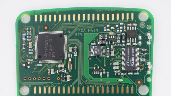
Back in the late 80s, our company managed to procure the complete 28 volume MIT Radiation Laboratory (Rad Lab) series, published in 1947, for the company library. To me, these books were interesting because I like history and old technology, but I didn’t understand why everyone was so excited about the acquisition. Only a cursory glimpse at the volumes would reveal that the “circuits” these books described used vacuum tubes and their “computers” were made from mechanical linkages. This was the 1980s, and we worked with modern radar and communications systems using semiconductors, integrated circuits, and digital computers. How could these old musty books possibly be of any practical use? To my surprise, it turned out that indeed they could, and eventually I came to appreciate the excitement. I even used several of them myself over the years.

Radiation Lab? Nuclear Radar?

In the years leading up to WW2, the idea of a civilian organization of scientists that would operate independently of the military and government bureaucracies was being championed by Dr. Vannevar Bush. The military and scientists had not worked well together during the first World War, and it looked like science and technology would be playing a much bigger role in the future.

It seemed certain that America would enter the conflict eventually, and Dr Bush and others believed that a new organizational framework was called for. To that end, the National Defense Research Committee (NDRC), which later became the Office of Scientific Research and Development (OSRD) was pitched to President Roosevelt and he approved it in June of 1940.

Almost immediately, a gift fell in the lap of the new organization — the Tizard Mission which arrived in the states from the UK in Sep 1940. They brought a literal treasure chest of technical innovations from the British, who hoped that US industry’s cooperation could help them survive what looked like certain and imminent invasion. One of those treasures was the cavity magnetron, which our own Dan Maloney wrote about a few years ago.

Within a few weeks, under the guidance of young Welshman “Taffy” Bowen, they had reviewed the design and gathered up the necessary equipment to fire it up. A 10 kV anode power supply and a 1,500 gauss electromagnet were procured, and the scientists gathered at the Bell Radio Laboratories in Whippany New Jersey on Sunday, Oct. 6, 1940. They powered up the cavity magnetron and were blown away by the results — over 10 kW of RF at 3 GHz (10 cm) from something the size of a bar of soap. Continue reading “Remembering The MIT Radiation Laboratory”

1960s Stereo Console Gets An Upgrade

Faced with an old console stereo from the 1960s that was barely functional, [Sherman Banks] aka W4ATL decided to upgrade its guts while keeping its appearance as close to the original as possible. This stereo set is a piece of mahogany furniture containing an AM/FM stereo receiver and an automatic turntable from JCPenny’s Penncrest line. As best [Sherman] can determine, it is most likely a 1965 model. The old electronics were getting more and more difficult to repair and the tuner was drifting off-station every 15 minutes. He didn’t want to throw it away, so he decided to replace all the innards.

The first thing was to tear out the old electronics while retaining the chassis proper. The new heart of the entertainment center is a modern Denon AV stereo receiver. This unit can be controlled over Ethernet, has a radio tuner, inputs for SiriusXM and a turntable, and supports Bluetooth streaming. [Sherman] next replaced the 1965 turntable, and then turned his attention to connecting up the controls and indicators.

The potentiometers were replaced with equivalent ones of lower resistance, the neon stereo indicator was replaced with an LED, but the linear tuning dial proved to be a nearly two month challenge and resulted in a cool hack. In brief, he connected an optical rotary encoder to the tuning knob and used a stepper motor with a linear actuator to control the dial indicator. All this is controlled from an Arduino Mega 2560 with three shields for I/O and LAN. But there was still one remaining issue — without vacuum tubes to warm up, the radio would play immediately after power-on. [Sherman] fixed that by programming the Arduino to slowly ramp up the volume at the same rate as the original tube receiver. And finally, he installs a small HDMI monitor in the corner to display auxiliary information and metadata from the Denon receiver.

Check out the videos below the break. We wrote about a couple of similar conversions in the past: this one from 2018 was also a Penncrest, and from last year this COVID isolation project that emphasized the addition of a new liquor cabinet.

Continue reading “1960s Stereo Console Gets An Upgrade”

PCB Stepper Motor Micro Robots

[Kevin Lynagh] is interested in tiny PCB stepper motors, and after reviewing the various projects and patents to-date, decided to give it a try himself. These are basically a stepper motor that’s been unrolled and made flat — traces on the PCB act as the coils and tiny magnetic “robots” act as the rotor.

If you want to try this concept yourself, [Kevin]’s post contains an excellent survey of prior art and projects, as well as exploring the theory behind how these things work. He has taken a deep dive in to the theory, deep enough to grasp what’s going on and to build some preliminary prototypes with a bit of confidence. First off was just a hand-wound flat coil as a proof-of-concept. Next was a PCB version that worked almost exactly as planned, although he confesses to burning out a motor driver circuit before stepping back and making some calculations.

We covered one such project back in 2014 and wrote about a Hackaday.io magnetic robot project from reader [bobricius] in 2018. Have you ever used this technology for anything besides a demonstration? Let us know in the comments below.

Thanks to [Adrian] for sending us the tip.

Save Money And Have Fun Using IEEE-488

A few months ago, I was discussing the control of GPIB equipment with a colleague. Based on only on my gut feeling and the briefest of research, I told him that the pricey and proprietary GPIB controller solutions could easily be replaced by open-source tools and Linux. In the many weeks that followed, I almost abandoned my stance several times out of frustration. With some perseverance, breaking the problems into bite-sized chunks, and lots of online searching to learn from other people’s experiences, my plan eventually succeeded. I haven’t abandoned my original stance entirely, I’ve taken a few steps back and added some qualifiers.

What is GPIB?

Example of HP-IB block diagram from the 1970s, from hp9845.net

Back in the 1960s, if test equipment was interconnected at all, there weren’t any agreed-upon methods for doing so. By the late 60s, the situation was made somewhat better by card-cage controller systems. These held a number of interface cards, one per instrument, presenting a common interface on the backplane. Although this approach was workable, the HP engineers realized they could significantly improve the concept to include these “bridging circuit boards” within the instruments and replacing the card cage backplane with passive cables. Thus began the development of what became the Hewlett-Packard Interface Bus (HP-IB). The October 1972 issue of the HP Journal introduced HP-IB with two main articles: A Practical Interface System for Electronic Instruments and A Common Digital Interface for Programmable Instruments: The Evolution of a System. Continue reading “Save Money And Have Fun Using IEEE-488”