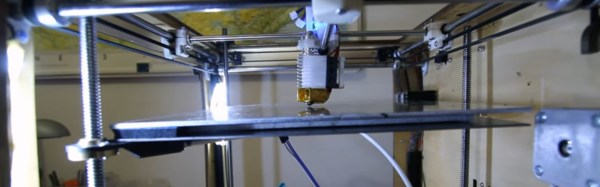
[Jeremie Francois] has been thinking about ways to improve tool height adjustment and bed leveling in his 3D printer for a long time. His dream was to never ever think about Z height again. A dream that’s shared by many. These days, a lot of 3D printers have a mechanism for auto leveling in the software of the 3D printer. This works pretty well, but for various mechanical reasons, it’s better to have the bed itself be level.
[Jeremie]’s approach is pretty clever. Since you can define any plane mathematically with three points, he has three Z-axis lead screws. This lets him tilt the bed at any angle he likes. Once he had the mechanics in place, he added some force sensitive resistors, an Arduino, and wrote an extension for the popular Marlin firmware. That’s when the problems started.
It turns out that solidly mounting the bed to the resistors transmitted way too many vibrations. The solution was a layer of neoprene rubber. The neoprene also acts as a cushion, so the nozzle won’t break the glass bed during the leveling procedure.
The video after the break is a bit wavy, due to YouTube’s terrible auto-stabilizing software, but if you watch closely, you can see the system at work.
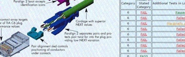
Though we’ve never used their cables, [Blue Jeans Cable] out of Seattle, WA sure does seem to take the black art of cable manufacture seriously. When they read the Cat 6 specification, they knew they couldn’t just keep building the cables the way they used to. So they did some research and purchased a Fluke certification tester for a measly 12,000 US dollars. While they were purchasing the device, they ran across an interesting tidbit in the fluke knowledge base. Fluke said that 80% of the consumer Cat 6 cables they tested didn’t begin to meet the Cat 6 specification.
This is the part where [Blue Jeans Cable] earns our respect; like good scientists, they set out to replicate Fluke’s results. Sure enough, 80% of the Cat 6 cables they tested from big box stores etc. failed the specification. More surprising, many of them didn’t even pass the Cat 5e specification. [Blue Jeans Cable] asserts that this is possible because the Ethernet cable specification is policed via the honor system, allowing manufacturers to be fairly brazen about what they label as Cat 6.
Despite tuning my extruder steps perfectly, and getting good results instantly on larger prints. I was still having a ton of trouble with smaller parts. PLA is the favored printing material for its low odor, low warping, and decent material properties. It also has many downside, but it’s biggest, for the end user, lies in its large glass transition temperature range. Like all thermoplastics, it shrinks when it cools, but because of this large range, it stays expanded and, getting deep into my reserve of technical terms, bendy for a long time. If you don’t cool it, the plastic will pile up in its expanded state and deform.
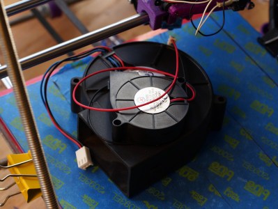
The old cooling fan on my trusty and thoroughly battered Prusa i2.
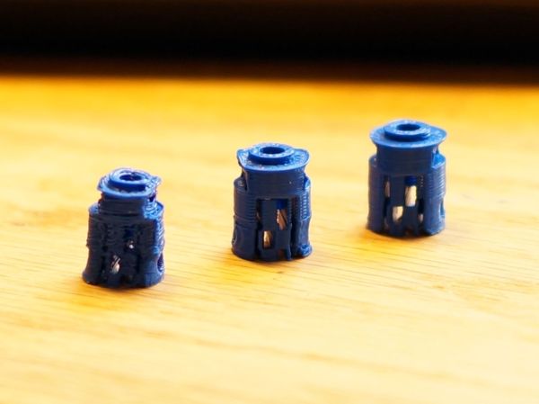
I am working on a project that needs a tiny part, pictured above. The part on the left is what I was getting with my current cooling set-up and temperature settings. It had very little semblance with the CAD file that brought it into this world.
The bond between layers in a 3d print occurs when the plastic has freshly left the nozzle at its melting point. Almost immediately after that, the plastic crosses from the liquid state into a glass state, and like pressing two pieces of glass together, no further bonding occurs. This means that in order to get a strong bond between the print layers, the plastic has to have enough thermal mass to melt the plastic below it. Allowing the polymer chains to get cozy and hold hands. Nozzle geometry can help some, by providing a heat source to press and melt the two layer together, but for the most part, the fusing is done by the liquid plastic. This is why large diameter nozzles produce stronger parts.
What I’m getting at is that I like to run my nozzle temperature a little hotter than is exactly needed or even sensible. This tends to produce a better bond and sometimes helps prevent jamming (with a good extruder design). It also reduces accuracy and adds gloopiness. So, my first attempt to fix the problem was to perhaps consider the possibility that I was not 100% right in running my nozzle so hot, and I dropped the temperature as low as I could push it. This produced a more dimensionally accurate part, but a extraordinarily weak one. I experimented with a range of temperatures, but found that all but the lowest produced goopy parts.
After confirming that I could not get a significant return on quality by fine tuning my temperature, I reduced the speed of the nozzle by a large percentage. By reducing the speed I was able to produce the middle of the three printed parts shown in the opening image. Moving the nozzle very slowly gave the ambient air and my old cooling fan plenty of time to cool the part. However, what was previously a five minute part now took twenty minutes to print. A larger part would be a nightmare.
This will do.
So, if I can’t adjust the temperature to get what I want, and I can adjust the speed; this tells me I just need to cool the part better. The glass state of the plastic is useless to me for two reasons. One, as stated before, no bonding occurs. Two, while the plastic remains expanded and bendy, the new layer being put down is being put down in the wrong place. When the plastic shrinks to its final dimension is when I want to place the next layer. Time to solve this the traditional way: overkill.
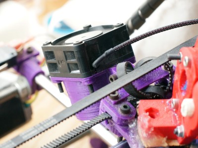
A while back my friend gifted me a little squirrel cage fan he had used with success on his 3d printer. Inspired by this, I had also scrounged a 12v, 1.7A fan from a broken Power Mac G5 power supply. When it spins up I have to be careful that it doesn’t throw itself off the table.
I should have added a rib to this bracket, this fan is heavy!
I printed out mounts for the fans. The big one got attached to the Z axis, and the little one rides behind the extruder. I fired up the gcode from before and started to print, only to find that my nozzle stopped extruding mid way. What? I soon discovered I had so much cooling that my nozzle was dropping below the 160C cold extrusion cut-off point and the firmware was stopping it from damaging itself. My heated bed also could no longer maintain a temperature higher than 59C. At this point I felt I was onto something.
I wrapped my extruder in fiberglass insulation and kapton tape, confidently turned the nozzle temperature up, set the speed to full, and clicked print. With the addition of the overkill cooling I was able to get the part shown to the right in my three example prints. This was full speed and achieved full bond. Not bad! Thus concludes this chapter in my adventures with cooling. I was really impressed by the results. Next I want to try cooling ABS as it prints. Some have reported horrible results, others pretty good ones, I’m interested. I also wonder about cooling the plastic with a liquid at a temperature just below the glass state as it is deposited. Thoughts?
My printer has other issues that I’m still tuning out, but the warping in PLA and excessive surface roughness has all the signs of over extrusion.
I have an old Prusa i2 that, like an old car, has been getting some major part replacements lately after many many hours of service. Recently both the extruder and the extruder motor died. The extruder died of brass fill filament sintering to the inside of the nozzle (always flush your extruder of exotic filaments). The motor died at the wires of constant flexing. Regardless, I replaced the motors and found myself with an issue; the new motor and hotend (junk motor from the junk bin, and an E3D v6, which is fantastic) worked way better and was pushing out too much filament.
The hotend, driver gear, extruder mechanics, back pressure, motor, and plastic type all work together to set how much plastic you can push through the nozzle at once. Even the speed at which the plastic is going through the nozzle can change how much friction that plastic experiences. Most of these effects are somewhat negligible. The printer does, however, have a sort of baseline steps per mm of plastic you can set.
The goal is to have a steps per mm that is exactly matched to how much plastic the printer pushes out. If you say 10mm, 10mm of filament should be eaten by the extruder. This setting is the “steps per mm” in the firmware configuration. This number should be close to perfect. Once it is, you can tune it by setting the “extrusion multiplier” setting in most slicers when you switch materials, or have environmental differences to compensate for.
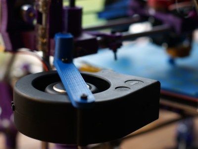
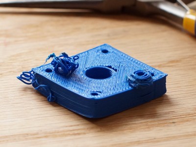
This little guy lets you tune the steps per mm exactly.
The problem comes in measuring the filament that is extruded. Filament comes off a spool and is pulled through an imprecisely held nozzle in an imprecisely made extruder assembly. On top of all that, the filament twists and curves. This makes it difficult to hold against a ruler or caliper and get a trustworthy measurement.
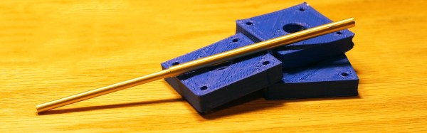
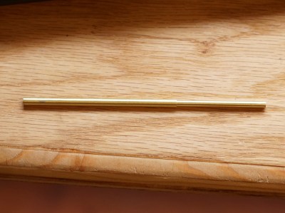
I have come up with a little measuring device you can make with some brass tubing, sandpaper, a saw (or pipe cutter), a pencil torch, solder, and some calipers. To start with, find two pieces of tubing. The first’s ID must fit closely with the filament size you use. The second tube must allow the inside tubing to slide inside of it closely. A close fit is essential.
[Giles Clement] was avoiding work in a bar, nursing a pint, and doodling a sketch for a camera. He looked at his sketch, thought, “gee, that looks better than answering emails,” and called his friend. An hour later they were at home depot buying supplies, and ten hours of furious work later, they had a camera. Nothing gets a project done like avoiding work! (See it all happen before your eyes in the video below the break.)
The camera is built around a 500mm f/4.5 Goerz Dogmar lens from around 1918 and was apparently used for aerial recon out of blimps. The frame of the camera is pine and plywood. [Giles] had heard that building the bellows for these cameras had taken other hobbyists months and thousands of dollars. Rather than elaborately folded fabric, he supported his 6 mil plastic bellows on telescoping rigid rods. To view the image while he’s focusing it, he sanded a plate of glass with 100 grit sandpaper to serve as a view screen.
Once the camera was completed, they prepared the plates and exposed photos. The first step, from what we could tell, was to disregard all chemical safety practices. The second step was pouring a substance called collodion on an unsanded glass plate and tilting the plate back and forth until the whole plate had an even coat on it. Then it was put in a bath of silver nitrate to sensitize. Once sensitized the plate was placed in the frame of the focused camera and an astonishing amount of strobe light emitted. After that it’s back to the chemical baths for more safety hazards. The whole process has to be done under fifteen minutes or the plate cures before it can be used. The photos that come out are seriously cool. It’s no wonder these old styles of photography have seen a comeback.
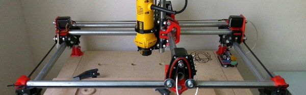
[Allted] has designed a CNC machine that you can print yourself; adding conduit, bearings, and the standard vitamins to bring it to life. The CNC machine uses a mechanical design similar to an etch-a-sketch, though instead of the maze of pulleys and cable it uses four stepper motors to do the X and Y translation. The machine looks to be about as accurate as a Shapeoko, and is able to handle light cutting in aluminum.
The coolest part is the extensibility of the printer. For example, [Allted] needed to print a lot of parts to make orders of the kit. So, he built a 4 headed 3D printer by copying blocks of the design, and tying them all to the same belt. The design also seems to be a little more resistant to dust and debris than some homemade rigs. The CNC won the Boca Bearings design competition. If you’d like to build one yourself, [Allted] has all the instructions with print setting recommendations on his website.
[NightHawkInLight] has been playing around with the diamagnetic properties of bismuth. Diamagnetic materials get a lot of attention due to their strange ability to produce the opposite of the magnetic field going through them. In simpler terms, metals like iron are attracted to magnets; metals like bismuth repel them.
[NightHawkInLight] built his own interpretation of a common lab example used to demonstrate this remarkable property, a levitator. A levitator is made by sandwiching a magnet between two plates of diamagnetic material. One of the plates is given a magnetic field opposite of the magnet underneath it by a stronger magnet placed some distance away. When this is done, the magnet in between wants to repel away from the plate above, only to find that as it gets closer to the plate below it is equally repelled, creating a stable system.